| .: Home :. | .: Productions :. | .: Misc :. |
Aélis

About
Aélis is a DIY effect pedal for processing voice (microphone input) but it can be easily adapted to electric instruments like guitar or bass. This page contains the building instructions.
Originally, it was a birthday gift for Alice, the singer from the SheWolf band. Because I couldn’t find schematics for a decent reverb for the voice, I designed one a we built it with the other band members.
Technically, the circuit is based on a Spin FV-1 processor. We could add other effects since it is programmable. The microphone preamplifier is simple but efficient. However it is lacking phantom power.

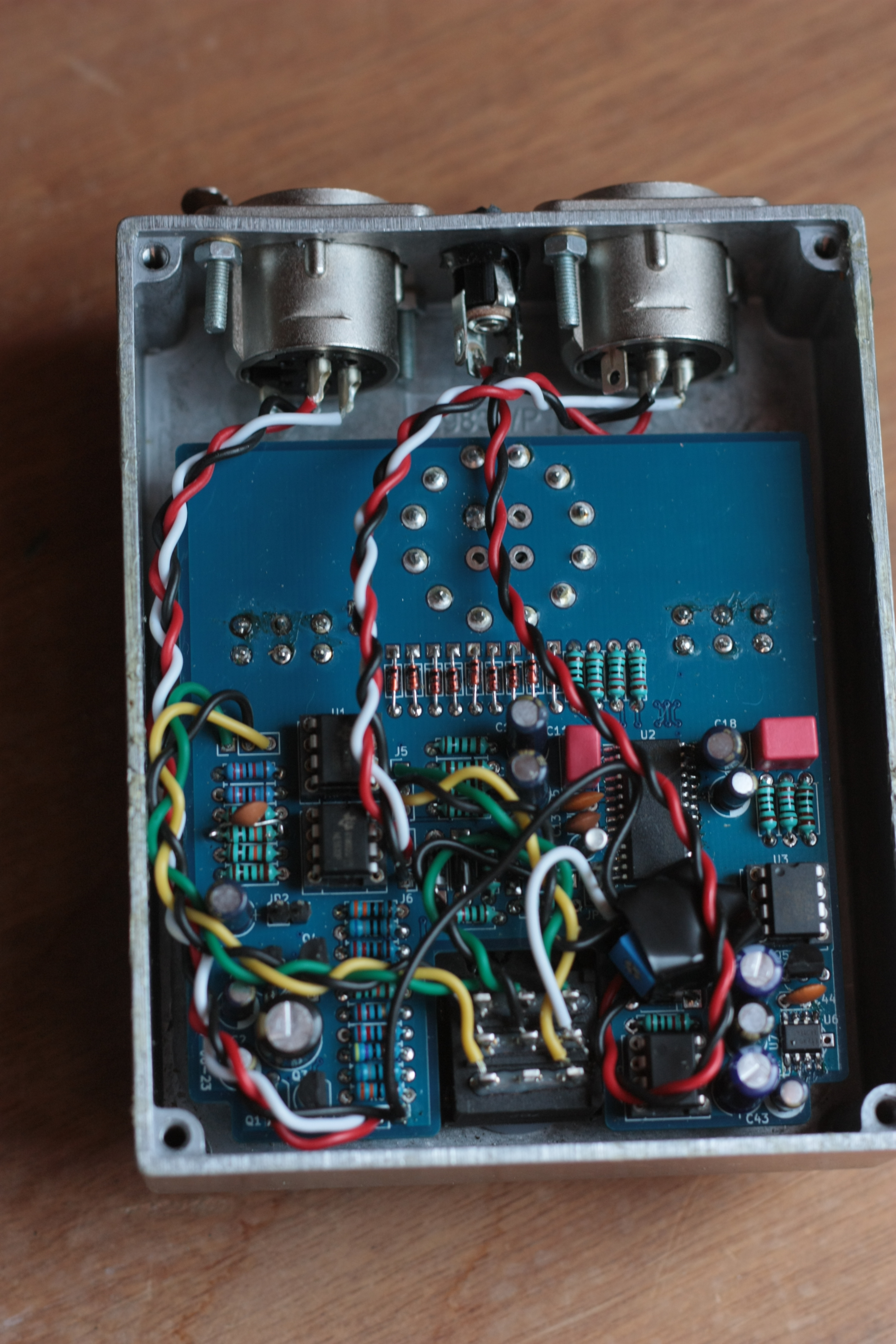
Above, the prototype version with a few patches on the circuit. Artwork by Diane Aberdam.
Ressources
Bill of materials

| Name | Qty | Value | Specific contraints or model |
|---|---|---|---|
| C5, C13 | 2 | 18p | Ceramic, pitch 2.5mm |
| C11 | 1 | 1n | Film, 7.2×4.5mm² pitch 5mm |
| C19 | 1 | 2n2 | Film, 7.2×4.5mm² pitch 5mm |
| C1, C15, C16, C30, C42, C44 | 6 | 100n | Ceramic, pitch 2.5mm |
| C4, C10, C12, C18 | 4 | 3u3 | Electrolytic, 16V, ⌀ 5mm, pitch 2mm |
| C2, C3, C14, C17, C45 | 5 | 10u | Electrolytic, 16V, ⌀ 5mm, pitch 2mm |
| C41 | 1 | 47u | Electrolytic, 25V, ⌀ 5mm, pitch 2mm |
| C40, C43 | 2 | 220u | Electrolytic, 16V, ⌀ 6.3mm, pitch 2.5mm |
| C0 | 1 | 470u | Electrolytic, 10V, ⌀ 8mm, pitch 3.5mm |
| Q1, Q2 | 2 | PNP transistor | Pinout EBC, 2N4403 |
| Q3, Q4, Q5 | 3 | NPN transistor | Pinout CBE, high gain, BC550C |
| Y1 | 1 | 32768Hz crystal | ⌀ 3.2mm, pitch 1.1mm |
| RV1 | 1 | 10k pot | Inverted logarithmic (C type), ⌀ 16mm, vertical on PCB, 16mm min pin length. Alpha 16mm type 4 |
| RV2, RV3, RV4 | 3 | 50k pot | Linear, ⌀ 16mm, vertical on PCB, 16mm min pin length. Alpha 16mm type 4 |
| SW1 | 1 | 12-position switch | Lorlin CK1049 |
| D10, D22 | 2 | LED | 5mm, rated current 20–40mA |
| D11–D19 | 9 | Standard diode | 1N4148 or 1N4448 |
| D20, D21, D30 | 3 | Schottky diode | 1N5817 |
| JP1, JP2 | 2 | 2×1 pin header | |
| R8 | 1 | 22 | 1%, ¼W |
| R21, R23, R29, R40, R41 | 5 | 100 | 1%, ¼W |
| R2, R3 | 2 | 680 | 1%, ¼W |
| R15, R20, R25, R42, R43 | 5 | 1k | 1%, ¼W |
| R4, R5 | 2 | 2k2 | 1%, ¼W |
| R0, R1, R45 | 3 | 3k3 | 1%, ¼W |
| R6, R7 | 2 | 4k7 | 1%, ¼W |
| R22, R24, R26, R27, R28, R50 | 6 | 10k | 1%, ¼W |
| R10, R11 | 2 | 22k | 1%, ¼W |
| R9, R12, R13, R14, R44 | 5 | 100k | 1%, ¼W |
| U1, U4 | 2 | Operational amplifier | Dual, DIL 8, NE5532 |
| U2 | 1 | DSP | Spin FV-1 |
| U3 | 1 | EEPROM | I²C interface, DIL 8, 24LC32A min |
| U5 | 1 | Negative voltage converter | LT1054, DIL 8 |
| U6 or U7 | 1 | LDO 3.3V | L4931ABD33 (SOIC-8), L4931CZ33 (TO-92) or even LP2950CZ33 (TO-92) |
| U1, U3, U4 | 3 | DIL 8 socket | Hollow body in order to put a 100nF capacitor inside |
| Footswitch | 1 | 3PDT | 20mm max |
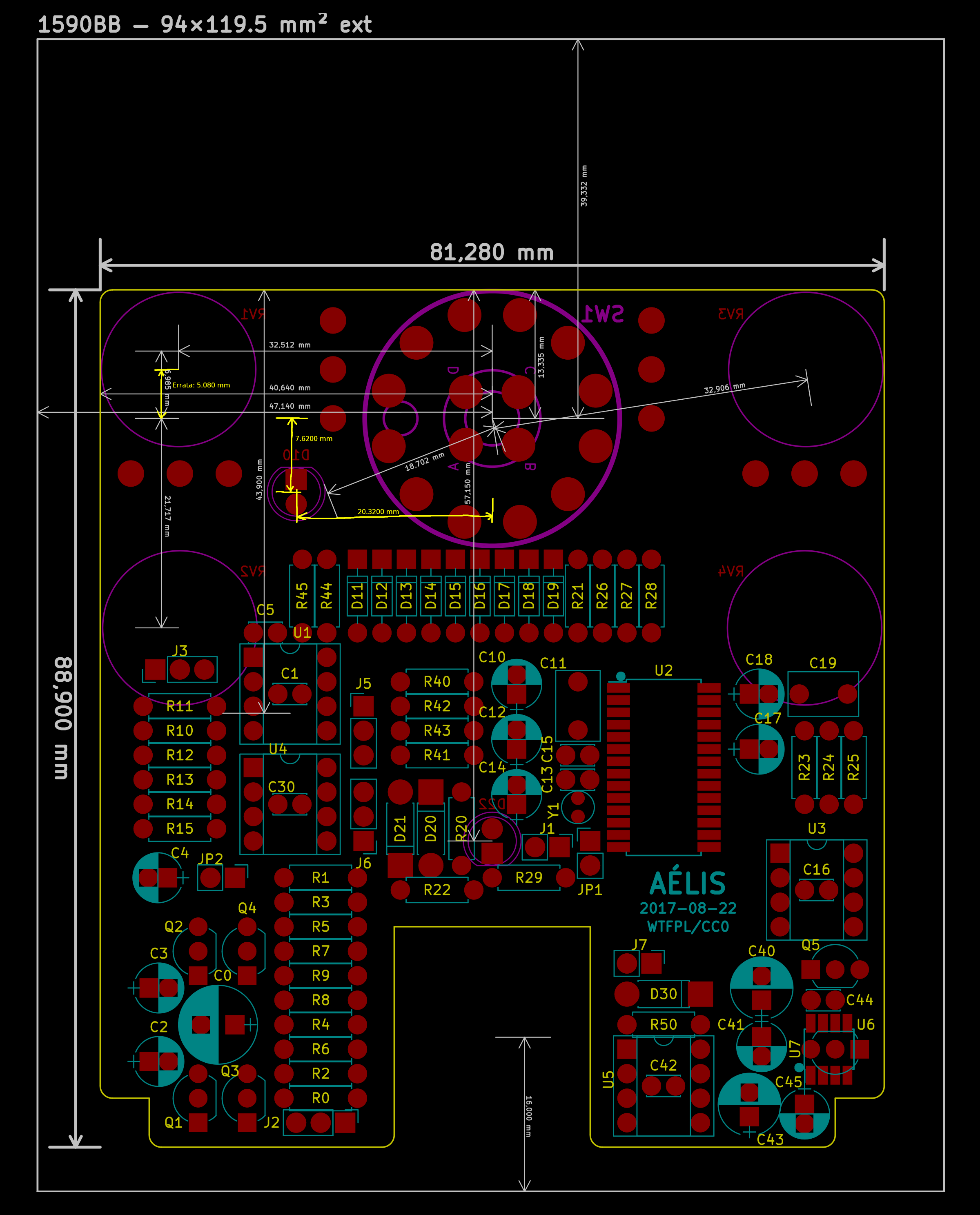
| Enclosure | 1 | 1590BB | Min ext size 94×119.5×34mm³, 2mm thickness. To be drilled. |
| Wire | About 2m | Insulated | |
| Power input | 1 | 2.1mm male jack socket | Insulated from the enclosure |
| Audio input | 1 | XLR female socket | 26×30mm², max 20mm internal depth including the solder lugs. Neutrik NC3FD-L-1 |
| Audio output | 1 | XLR male socket | 26×30mm², max 20mm internal depth including the solder lugs. Neutrik NC3MD-L-1 |
| Knobs for the potentiometers | 4 | ||
| Knob for the switch | 1 | ⌀ 6mm shaft, with screw | |
| PCB | 1 | See below |
Important notes:
- Components must be at most 12mm tall so they fit in a standard 1590BB enclosure.
- Resistors and diodes (excluding LEDs) must be at most 7mm long. If not, they must be soldered vertically.
- Resistors should be 1% accurate, particularly R0–R7 and R40–R41. But most of the time 5% is still acceptable.
- Potentiometer pins must be long enough to reach the PCB once fastened to the enclosure, because the 12-position switch is much taller.
- Potentiometer knobs must fit their shafts.
- Regarding U6 and U7, it is recommended to use the SOIC version which dissipates heat better. The PCB includes footprints for both packages, just populate one of them. The LP2950CZ33 is an alternative solution. It exists as a TO-92 package with the same pinout and dissipates heat quite decently, but is slightly noiser than the L4931 (theoretically, not tested here).
- The 9V power is not filtered and requires to be of a decent quality to avoid hum. If required, add a 20Ω resistor in series on the +9V.
- Make sure that the chosen buttons don’t touch each others and that they don’t touch the LEDs.
Count about 60€ of good quality components (2017).
Tools: soldering material, cross-head screwdriver, cutting pliers, drill, drill bits from 3 to 12mm for the metal, round file for the metal, a set of wrenches or adjustable wrench, tools to strip wires, insulated tape, metal saw.
Schematics and PCB
Electronic schematics, Gerber files for the print, layouts, FV-1 programs and KiCAD source files are located in the following archive: aelis-2020-06-14.zip (1214kB).
I can provide PCBs at cost price + shipping fees.
Please contact me if you are interested.
Sorry, all boards are sold out now.


Building
Instructions
The pedal is put together pretty tight in a 1590BB enclosure. There is no room for a battery, power supply must be external. Holes must be placed as accurately as possible. The XLR sockets must be located behind the enclosure. They pack tightly vertically, make sure they fit well. Use a round file to finish drilling their complex hole.
Dimensions to locate holes for the potentiometers, LEDs, and switches are given on the layout picture.
First solder the SMD components: the FV-1 and possibly the L4931. Solder the remaining components on the top layer of the PCB, sorted by height. Carefully cut the legs of components that will overlap with the potentiometers. Cut the wires to the right length and solder them to the PCB.
Solder the wires to the connectors mounted by the outside (like the XLR). Now the enclosure is assumed finished (drilling, painting, …), because the PCB will be attached permanently.
With cutting pliers, cut the anti-rotation bits from the potentiometers and the rotative switch. With the saw, cut the switch shaft. Adjust its ring in order to limit the range to 8 positions. Fasten all these components to the enclosure. Put insulated tape at the back of RV2 and RV4 to make sure they won’t make contact with the soldered leg ends on the PCB.
Put the LEDs then the PCB. First solder the rotary switch, then the potentiometers and the LEDs. Put the footswitch and solder the remaining wires.
When everything is ready, screw the knobs on the shafts.
EEPROM programming
Because I don’t own a dedicated EEPROM programmer, I made a very simple board using the I²C interface on the Raspberry Pi 3 GPIO (works with any Pi model).

Pull-up resistors are 10kΩ.
Effects were designed with
SpinCAD Designer
on Windows.
They were exported as HEX files and copied on the Pi.
From there, I used hextobin, a program that can be found
in the archive, to convert the HEX file into a raw binary file.
The resulting file is tansferred to the EEPROM with
eeprog.
If EEPROM programming is not possible (or for testing purpose), you can still use the FV-1 factory presets by adding a jumper to JP1.
Modification for guitar and bass
The pedal can be adapted to instruments impedance and levels. The PCB is the same, there is only a few components (mainly the preamp section) to remove or change. Check all the pages of the schematics for a complete description of the modifications. XLR sockets should be replaced with female mono jack connectors.
Use
First, adjust the input gain (top right knob). Set it as high as possible without lighting the clipping LED (keep some margin tho).
The middle knob selects the effect. The other knobs have different roles depending on the current effect. Generally, the bottom right knob is a dry/wet mix. For reverb effects, the top left knob is the reverberation time, and the bottom left knob controls the filter.
The effect is lacking proper phantom power support. It is not recommended to provide a phantom power on its output, however this should not damage it.
| [Home] [Productions] [Misc] | Website by Laurent de Soras, 2003-2019 |