Pédale Vite v2 — User manual
Content
- Introduction
- Usage
- Reference
- Available effects
- All-Pass Distortion
- Bad Radio — Distortion
- Bazz Fuzz — Distortion
- Big Muff Pi — Distortion
- Channel Merge
- Channel Split
- Color Me — Vocal filter
- CompEx — Dynamics compressor/expander
- Convert To Mono
- Convert To Stereo
- Crystalise — Tone alteration
- Delay — Stereo delay
- Diode clipper — Diode distortion
- Distortion 3
- Distortion Tone Stage
- Double Distortion
- Envelope Follower
- Filter Squeezer — Distorted resonant filter
- FlanCho — Chorus and flanger
- Freeverb — Reverberation
- Frequency Shifter
- Frequency Splitter
- Harmonic Tremolo — Two-band tremolo
- Hypercomb — Polyphonic comb filter
- Input Impedance Fix
- Lipidipi — Fat ensemble effect
- Mid Side Coder
- Moog Filter — Filter
- Noise Bleach — Noise gate
- Noise Chlorine — Noise gate
- Onset detector
- Parametric Equalizer
- Phaser AP
- Phaser HT
- Pitch Detector
- Platitude — Plate reverberator
- Pulse Width Modulation Distortion
- Pulse Width Modulation Distortion 2
- Skool-Mood — Phaser
- SiemensGirlz — Creative delay
- Simple Distortion
- Speaker Emulator
- Spectral Crusher
- Spectral Freeze — Tone freeze
- Stereo Panning
- Test Generator — Test signal generator
- Tremolo
- Velvet Freeze — Tone freeze
- Vocoder
- Volume Clone — Volume follower utility
- Wah-wah
- Wah-wah (CryBaby)
- ADSR — Control envelope
- Control ramp — Parameter transition
- LFO — Low frequency oscillator
- Troubleshooting
- Change log
I. Introduction
Pédale Vite is a DIY multi-effect pedalboard for guitar. This manual explains how to use the pedalboard once assembled and functional.
II. Usage
Hardware description
Back panel
- Guitar audio input
- Audio output to amplifier or mixing desk
- Jacks for expression pedals
- Fuse holder
- 220–240 V power lead
- Power switch

The first expression pedal is on the left hand side of the panel, and therefore on the right hand side when facing the pedalboard. Same for the audio inputs and outputs.
All jacks are balanced ¼”.
Impedences of the audio inputs are above 2 MΩ for the jacks, 2.2 kΩ for the XLR with the mic preamp. Use the first channel to connect the guitar or any other mono signal. When the pedalboard is set to mono, both outputs send the same signal.
Important: do not plug a Pédale Vite output on a device (mixing console or other) input whose phantom power is turned on. It would damage the outputs; they are not coupled with capacitors.
Front panel
- Effect control knob
- Display
- Navigation knobs
- Navigation buttons
- Control LED, their use depends on the context.
- Two rows of six footswitches to change the effects.

The navigation buttons are arranged as follows. Top row : Select/validate (Select), top arrow (↑), cancel/escape (Esc). Bottom row : left arrow (←), down arrow (↓), right arrow (→).
Navigation knobs are usually redundant with navigation buttons. The left one allows to move vertically, and the right one to move horizontally or to change a value. These knobs may also be pressed, as keys. Depending on the context, the left (LShift) and right (RShift) keys alter the functionalities of other keys. Unless specifically mentionned, holding LShift depressed activates the page scrolling, and RShift makes finer parameter modifications.
Startup
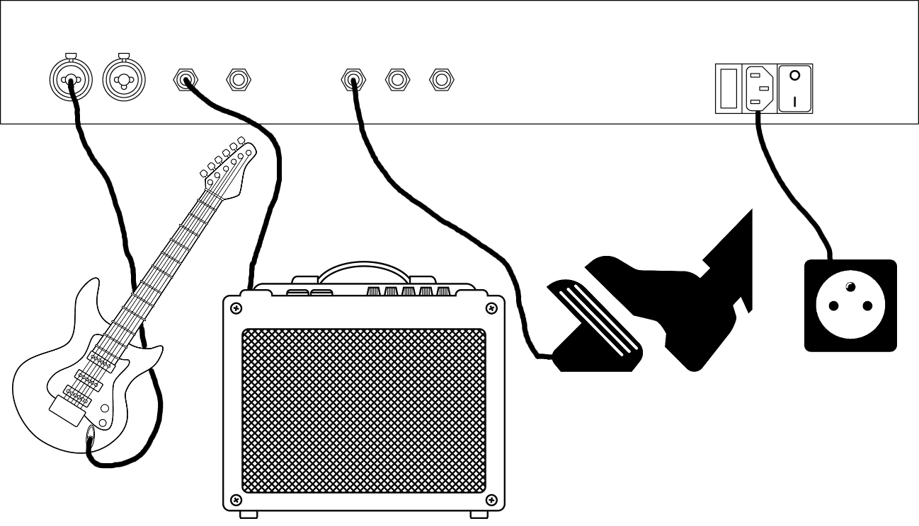
- Connect the power lead (5).
- Plug the guitar on the left input (1).
- Plug the left output (2) on an amplifier.
- Switch on the pedalboard (6).
After less than ten seconds, the display should show the current program, called <Empty prog>, a simple bypass.

- Switch on the amplifier.
- Play.
Sound is too loud? Too quiet? You don’t hear anything? Please report to the calibration section.
To stop, perform operations in reverse order: switch off the amplifier, switch off the pedalboard and unplug it.
Note: it is not recommended to have the amplifier running while the pedalboard is switched on or off.
Calibration
In order for the pedalboard to give optimum results, it must be calibrated, especially the input and output levels. The goal is to have as strong an input level as possible without the incoming guitar signal saturating at that point. Then, if you play on an amp, you have to go out at a level similar to the guitar plugged in directly.
Press the Select button, scroll down to the Volume & Levels menu, and press Select again.

This takes you to the level control screen. The upper meter shows the input levels, the middle one the output levels. The levels to be considered (peaks) are given by the small strokes moving to the right of the solid bars (RMS).

Input level
Play as hard as possible. Input level should never exceed 0 dB, and rarely go above −6 dB. However it should be as high as possible.
Input level is set at the minimum by default, which is fine for an electric guitar plugged directly to the pedalboard. Anyway, it may be required to adjust it, for example if your guitar has a too low output.
Turn the input 1 gain knob until the level looks correct. Then set the same level on the input 2.
Output level
Once we are done with the input level, we can set the output level. Make sure an empty program (“Bypass”) is activated, so the guitar input goes directly to the output without any modification.
Go to the Output volume settings with the vertical arrows. Change the volume with the horizontal arrows.
Then set the output level on the audio interface in order to get the same sound as with a guitar plugged directly to the amplifier. An AB/Y box is a great help for this. If you don’t have one, you can plug alternatively the guitar on the pedalboard and on the amplifier to compare the volumes.
First steps
…
III. Reference
Concept
Effects on the pedalboard are organized in programs. A program is made of an effect chain and some settings to control the effects from footswitches, pedals and knobs, the controllers.
Programs are grouped in banks. Each bank is made of 16 programs, and the pedalboard contains 64 banks. The pedalboard makes easy the navigation between the programs of a single bank.
A program is made of an effect chain. For each effect, it is possible to set its volume, the mix between the input signal and the output signal, and to bypass the processing.
LEDs
There are three LEDs on the pedalboard, a green one surrounded by two red ones. Their meaning depends on the context, on the activated function. Usually they should be off, excepted when using the tuner.
Normal operations

The leftmost red LED indicates that the output sound clips. You should lower the main volume or the volume of one of the activated effects.

The green LED indicates that the pedalboard is performing a write operation on the internal drive (the SD card). Such an operation is usually quick, anyway make sure not to switch off the pedalboard at this moment. The memory card is delicate and could be damaged.

The rightmost red LED indicates that the processing unit is overloaded. There are too much simultaneous effects, or they have too complex settings, and the sound cannot be produced on time. It is suitable to recall a simpler program, or to change the effect parameters to reduce the load. It can also be a temporary overload, in which case there is nothing special to do. The sound should come back and the LED turn off. When the processing load is significant (above 75 %) without being critical, the LED light is dimmed.

However, if the overload lasts, the audio engine gives up its recovery attempt. This state is indicated with all the three LEDs lit. In this case, a simpler program should be activated and the audio engine restarted manually. This can be obtained by pressing Esc three times on the main screen.
Tuner
In tuner mode, the LEDs indicates the rightness of the played note. The leftmost LED indicates that the note is too low, and the rightmost one that the note is too high.
When the played note is right, the green LED is lit.
Main screens
Current program and information
This is the startup screen. This is also the one on the top of the menu hierarchy. If you get lost, just press Esc one or more times to get back here.

Several important information are displayed here: On the top, the current program and bank. On the middle, the controllers used by the program or the last modified parameter. On the bottom, the Raspberry Pi IP address, if it is available. Indeed it is required to connect on the machine with SSH for maintenance operations.
The Esc key in this screen activates some other functions. They depends how many times the key is pressed:
- Updates the display, particularly the IP address.
- Resets the display hardware.
- Resets the audio engine.
Main menu
This screen is reached by pressing Select in the current program screen. It can be exited with Esc. Navigation is done with ↑ and ↓. Select opens the page highlighted with the cursor.
| Edit program | Editing a program |
| Banks | Access to Program Banks |
| Pedal layout | Pedalboard Configuration |
| Volume & levels | Access to Volumes and Levels |
| Other settings | Other Settings |
| Tuner | Tuner |
| Restart | Restart options |
Editing a program
Effect chain

This is the main page to edit a program. Navigations is done with the ↑ and ↓ keys. Select enters the highlighted object et Esc gets back to the current program screen.
The first line is the program name, which can be edited.
Settings… gives access to various program-related settings.
Save to… saves the currently edited program.
The following list is the effect chain, in processing order. The sound is processed from the top, down to the bottom of the list. Effects are shown as a linear list, but their routing can be much more complex, with multiple branchs (graph). Each line is a distinct effet. <Empty> indicates that there is no effect on the line and <End> terminates the list. Disconnected effects, or effect chains not connected to the audio output are located at the end of the list.
The small discs next to each effects indicate the chain segment in which the selected effect is located. The displayed segment stops to the first fork in the audio processing : upstream when several effects are mixed together, and downstream when the signal is spread out to several effets. Effects involved in these possible forks are indicated with an outlined circle.
When the audio input and output are not linked by any effect chain, a warning message is displayed on the top line.
A line written in bold indicates that at least one controller applies on the effect.
The effect on the highlighted line (including <Empty> and <End>) can be changed with ← and →. These keys sweep all the available effects. If <End> is replaced with an effect, a new empty line is automatically inserted after. In return, it is possible to remove the effect from the last line. Select gives access to the effect configuration.
Finally, the last list shows the effects that don’t need audio to work, like the LFOs for example.
Configurations and parameters are memorized for each kind of effect. If the effect type is changed by mistake, settings are kept and applied back when the initial effect is restored. It’s also possible to try several effects by adjusting their parameters and comparing them without hasle.
Also, an effect of a new kind generally appears with the same configuration it had during its previous instantiation. To restart from default settings, one can use Reset from the Effect Configuration.
When the automatic parameter assign option is activated (see the Other settings screen), the 5 rotary encoders are assigned temporarily to the 5 first parameters of the selected effect.
Save Program
When a program is saved, the program list from the current bank is displayed.

The very first line indicates the bank where the program will be saved. It is possible to change the bank with the horizontal arrows.
The program slot where the settings shall be overwritten is chosen with Select. The bold line indicates the active program. It is the default selection. Esc cancels the operation and gets back to the effect chain.
Once the saving location is validated, one can type the the program name.

The screen title reminds the storage location. The name correspounding to active settings is pre-filled. One can modify it by navigating in the list of characters. Select validates the highlighted character or action. Esc cancels the operation and gets back to the effect chain.
| OK | Validates the choice and does the data saving. The green LED lights up shortly during this time. |
| CANCEL | Cancels the operation. |
| SPC | Insert a space at the carret location. |
| DEL | Delete the character at the left of the carret. |
| ← and → | Move the carret. |
Parameter list

The first line FX setup… jumps to the Effect Configuration screen. For some effects, there can be a second line Graphic editing… to edit the parameters using a graphic representation. It’s the case for PEq for example.
The following three lines are common to all the effects and deal with the mixing parameters. The value is on the right of the parameter. The following lines are specific to the effect. A parameter written in bold indicates that it is modulated by at least one controller.
One can change the selected parameter with the horizontal arrows, and enter the Parameter Edit screen (more accurate values, controllers…) with Select.
Bypass
Deactivate the effect when set to On.
Effect mix
Mixes the effect output with its input. The parameters indicates the output ratio, in percent.
Volume
Adjustment output volume, in dB. This parameters helps to homogenize the volume, within the effect chain and between the different programs. This volume is applied before the input/output mix.
Parameter Edit

The name, the value and possibly the unit of the parameter are indicated on the top.
One can change the parameter value using four scale factors (the dots) and the horizontal arrows.
The Controllers… line allows to chose the direct links and modulations for the parameters by pressing Select. Bold face indicates that at least one controller is attached to the parameter. The last line is about time parameters. It indicates (if relevant) if the parameters follows the tempo or if it is independant from it.
Controller Choice

Two types of controllers can be selected here:
- Direct link: the controller drives directly the parameter value. There is at most one per parameter.
- Modulations: it’s a list of additive controllers modulating the value. There can be several of them and their order isn’t important.
One can navigate using the vertical arrows and go to the Controller Edit screen with Select. A line <Empty> indicates that there is no controller attached here. It is always there at the end of the modulation list to allow adding a new one. One can go back to the Parameter Edit screen with the Esc key.
Controller Edit


One can setup a controller (direct link or modulation) on this screen. A direct link controller requires two parameter values: a value for the controller’s low position, and another for the high position. The parameter will take all the values between these bounds. By default, the minimum and maximum parameter values are used.
A modulation controller requires only one setting, its depth, in percent of the parameter range.
The first line Src indicates the controller source. One can chose it by cycling within the list using the horizontal arrows. The available sources are the following ones:
| <Empty/Delete> | Only for editing. Indicates that there is no controller or it is to be deleted. | |
| Expression | 0–2 | Expression pedals. |
| Knob | 0–4 | Rotary encoders. |
| Footsw | 0–11 | Footswitches. |
There can be other modulation sources, depending on the program configuration: LFOs, envelope followers… These sources appear first on the list.
Step is only for rotary encoders. It selects its sensitivity. The fractional value indicates the fraction of the parameter range between two consecutive steps. It can be set with the horizontal arrows.
Below, there are the bounding values. They depend on the controller type. They are changed exactly like in the Parameter Edit screen.
Final indicates the final, modulated parameter value. If the parameter is modulated by multiple source, the final value reflects the contribution of all the modulations, not the edited one only.
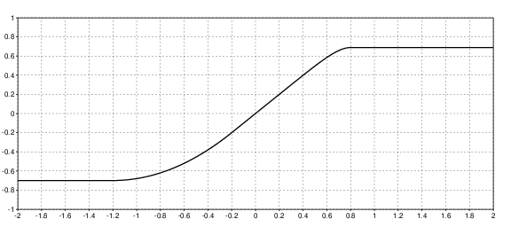
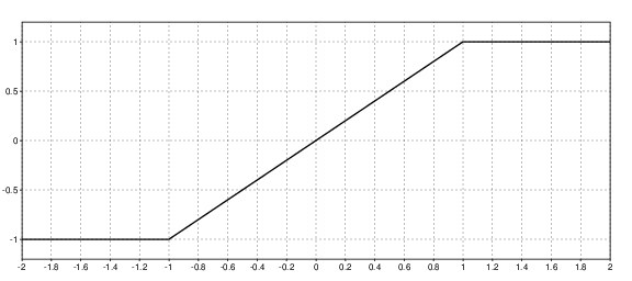
Curve selects the curve to apply on the source. It changes the controller sensitivity depending on the value ranges. It can be set with the horizontal arrows.
| Linear | Neutral curve, default. |
| Square | Parabolic curve. Accuracy in the low range, sensitivity in the high range. |
| Cubic | Like Square, but more pronounced. |
| Sq inv | Saturated curve. It is the opposite of Square: high range is accurate, and low range is sensitive. |
| Cb inv | Like the previous one, but more pronounced. |
| S 1 | Accuracy in the bottom and top ranges, sensitivity in the mid range. |
| S 2 | Same as S 1, but more pronounced. |
| Flat 1 | Mid range is accurate, and bottom and top ranges are sensitive. |
| Flat 2 | Like Flat 1, but more pronounced. |
| Prog 1 | Several curves with more or less progressive slopes. |
| Prog 2 | |
| Prog 3 | |
| Prog 4 | |
| Sat 1 | Several curves with more or less saturated slopes. |
| Sat 2 | |
| Sat 3 | |
| Sat 4 |
The curve graphic can be shown with Select.

Range is used only on modulation with some specific sources only. It can convert a unipolar signal (posivite values only) into a bipolar signal (positive and negative values). The signal shape is preserved, the value range is just stretched down to the negative range. This allows putting the neutral modulation value in the middle of the controller course. One can select Bipolar or Unipolar with the horizontal arrows.
Clip restricts the source range. The main purpose is to assign their own variation range to different parameters controlled by a unique source, thus achieving threshold effects. Clip is processed after the Range function. Src← and Src→ clip the modulation source range. These bounds are mapped to new vanues given by Dest↓ and Dest↑. Input values in this raneg are linearly interpolated. Modulations out of this range are clipped to Dest↓ or Dest↑.
Esc exits the screen. Modification are immediately taken into account in real time, there is no specific validation to do.
Effect Configuration

The first line indicates the effect type, which can be changed with the horizontal arrows. Press Select to access a menu where all the effects are sorted into categories. The current effect and its categories are listed in bold :

Insert before adds an empty block in the chain before the selected effect. This empty block becomes the current effect and is immediately editable. If the effect doesn’t use any audio source, its position is irrelevant and the entry is simply called Insert.
The following menu entries may or may not appear, depending on the nature and the current state of the effect :
Insert after adds an empty block in the chain after the selected effect. This empty block becomes the current effect.
Routing… reaches a the routing menu to connect, disconnect and move the effect within the audio graph.
Presets… leads to the preset menu.
Reset restores the default parameters.
Chan is useful for effects that can convert a mono signal to stereo (chorus, delay…) Auto selects the stereo, which will be effective only with a global stereo output. prefer mono keeps the mono signal in all the cases. If the input signal is already stereo, it keeps stereo, whatever the selected option. Use Select to change the settings.
State indicates if the effect memory must be cleaned (fresh) when the program is activated, or kept from the previous use (keep). Cleaning the memory may have an impact on the response time but should be light.
Name is the name of the effect instance. It can be used to identify it with global-range pedals and controllers, not depending on the program. For example, you can have a pedalboard-range footswitch to change the bypass state of any effect called “distortion”.
CPU indicates the computing capacity used by this effect only, in percent of the total available capacity for audio processing. The first figure is the average value, while the second one is the peak reached during the last two seconds.
Routing
In this screens you can connect ot disconnect the effect to other effects, or move it through the audio graph.

Move… moves the effect within the chain. After having pressed on Select, the chain appears and it is possible to move the effect with the vertical arrows. Changes are immediately effective. Select or Esc to exit.
The other lines below show the connections to each input and output pin. When the target effect has several pins, the pin number is displayed next to the connection after an hyphen.
Note : listed pins can be different of the real pin set of the effect. It means that some connections may lead to nothing if the effect cannot handle them. This allows changing easily the effect without destroying the connections each time they are incompatible with the new effect.
Press Select on a pin to add a connection you can select in the list. Only the new possible connections are shown, the ones not creating loops in the audio graph. Esc to cancel.

Press Select on a connection to delete it or to replace it by another one from the list. Esc to cancel.

There are two other types of input and output, Send and Return. This is a way to build loops across the effect connection graph and create internal feedback. Indeed, anything entering a Send exits from the corresponding Return, that can be located upstream. There are 4 different send-return paths available. The feedback is not instantaneous like in an analogue effect, there is a delay of about a millisecond. Because feedback can quickly build up and degenerate, any signal entering a Send is systematically clipped to +24 dBFS. Nevertheless, it is strongly recommended to insert a limiter just before in order to tame the signal.
Presets

In this menu you can manage the stored presets for the current effect.
| Load… | Loads a stored preset |
| Browse… | Browse through the stored preset list while automatically loading them |
| Store… | Saves the current settings |
| Swap… | Exchanges the current settings with a stored preset |
| Rename… | Renames a stored preset |
| Morph… | Not available, work in progress |
| Delete… | Deletes a stored preset |
| Organize… | Not available, work in progress |
Most of these entries lead to the list of the stored presets. In this list, press Select to do the selected action and come back to the menu. Press Esc to cancel the operation.

In Browse… mode, the setting change is immediate and is updated at each cursor movement. These settings are kept when quitting the list with Select. If you don’t want to keep them, press Esc to quit and restore the original settings.
Save and rename operation lead to another screen for editing the preset name.
Program banks

Organize banks and programs

This menu gives access to several operations allowing to organize banks and programs.
Move banks… is for moving banks within the bank list.
Move programs… is for moving programs within the current bank.
Program catalog gives accès to a complete list of all the programs from all the banks.
Move banks

First, with the vertical arrows, select a bank to move. Select to validate or Esc to return to the previous menu.

Once the bank is selected, use the vertical arrows to move this bank. Select to validate the move or Esc to cancel and return to the previous menu.
Move programs

First, with the vertical arrows, select a program to move. Select to validate or Esc to return to the previous menu.

Once the program is selected, use the vertical arrows to move it. Select to validate the move or Esc to cancel and return to the previous menu.
Program catalog
This page lists all the programs from all the banks, without duplicates nor empty programs. The first program of the list is activated when entering the page. Use the vertical arrows to browse. Programs are automatically activated when browsed through. Esc to return to the previous menu. Upon return, the current bank and current program reflect the last browsed program from the list.
Pedalboard configuration
This part is used to adjust the action of each footswitch at the global level. It is also possible to adjust these settings at the bank and program level, the menus are identical and the configured actions overlap.

The list above allows you to see at a glance what each footswitch does. The twelve footswitches are numbered in two rows: first the bottom (the closest), from 1 to 6 from the left to the right, then the top (farthest) from 7 to 12. Use the vertical arrows to navigate and Select to edit a footswitch.

In this menu, Full edit… allows editing the content of the footswitch and Clear/empty to reset it. The other functions are not implemented yet.

The menu above gives access to the three footswitch trigger modes and indicates whether or not this mode is used. The modes are the following:
| Press | Immediate action when pressed |
| Hold | Action after having hold it pressed for about 2 seconds |
| Release | Action when the footswitch is released |
The three modes can be used simultaneously to obtain different functions from the same footswitch. However when Hold is used, it is recommended to move the Press content to Release in order to avoid unwanted aliasing.
There is no automatic repeat like on a computer keyboard. A new action is triggered only after the footswitch state is actually changed.

Each triggering mode is linked to a cycle made of one or more Steps. When the footswitch is triggerred, a cycle step is activated, and the next trigger will activate the next step in the cycle, until the cycle is finished and starts again.
In a majority of cases, cycles only have one steps. On the other hand, the Hold and Release modes accept only one step.

The menu above allows you to modify a step. A step consists of one or more actions that will be carried out simultaneously when the step is activated. Below are the available actions:
| Bank | Activates a given bank, or switches to the next or the previous one. |
| Program | Activates a given program, or switches to the next or the previous one. |
| Tuner toggle | Activates or deactivates the tuner. |
| FX toggle | Activates or deactivates effects. The effects can be identified by their type or by their name. When several effects are targeted, they all switch to the same states. If some of the switching effects require to stay in the state opposite to the others, use a second FX toggle associated to a second label. |
| Loop record | (not available yet) |
| Loop play/stop | (not available yet) |
| Loop undo | (not available yet) |
| Parameter | Sets a parameter from a given effect. The effect can be identified by its type or by its name (label). |
| Tempo tap | When this function is associated to a footswitch, you can set the tempo by beating the switch. |
| Preset | Activates a preset for a given effect. The preset can be fixed, or the next or the previous one. The effect can be identified by its type or by its name. |
| Event | (not available yet) |
| Tempo set | Sets the tempo to a fixed value. |
| Click | Activates or deactivates the click. |
Volume and levels
This screen shows and controls the levels. The bars indicate the input and output volumes. When a bar is split, it means that the signal is stereo. This is always the case for the input, even if only the left channel is taken into account in the effect chain. The small The small line indicates the level of the peaks with a stationary time of 2 s, and the solid bar the RMS volume.
The DSP bar indicates the CPU resources eaten by the audio processing. The hatched part is the average load, and the solid part the peaks. They should stay as low as possible and never touch the right part of the gauge, otherwise clicks and sound loss may occur.
It is possible to set the Output volume with the horizontal arrows.
The symbols at the left of the DSP gauge indicate if the input and output are mono (one circle) or stereo (two interlaced circles).
When the cursor is on the DSP, the audio engine can be restarted by pressing on Select.
Other settings

Tempo sets the tempo in quarter notes per minute. It is possible to set the integer part or the fractional part of the tempo. Pressing Select on the fractional part rounds the tempo to the nearest integer.
Click activates or deactivates the click, based on the tempo setting. At the moment, the time signature is restricted to 4/4.
Save settings immediately saves the current settings. Indeed, most non-program modifications (for example the stereo mode or the output level) are not saved automatically. They are saved with the next program modifications or explicitely by selecting this menu entry.
Record to disk… leads to the audio recording menu.
Backup… enters the backup menu.
Automatic param assign enables the automatic mapping of the 5 rotary encoders to the 5 first parameters of the effect being edited in the Program edit page.
Backup menu

Before doing a backup copy, you must ensure that the date is correctly set, with the risk of being confused by an inconsistent timestamping.
The screen accessed with Set date… may be used to set the current date and time. Indeed, the internal computer does not have a system to keep the time between two sessions. So it may be necessary to set the date before doing a backup copy of the settings. However, if the machine is connected to the internet during startup, the date is automatically updated.
Important: time and date are UTC (coordinated universal time), not the local time.
In this screen, use the vertical arrows to select the field to edit, and the horizontal arrows to modify the values. The date is automatically updated when exiting the screen with Esc or Select. Because of technical reasons, the program is restarted after a date modification, so any unsaved change may be lost.

Save backup now does a backup copy.
The file is saved in the same directory as the main settings (namely
/opt/pedalevite/etc/config/), with the current date and time
following its name.
Restore backup… is still under construction.
Export to USB stick saves the backup on an external
USB drive.
It is automatically mounted (/mnt/sda1, FAT32) and unmounted during
the backup.
Record

This feature records both the raw audio input and output.
The audio is recorded in a unique file,
/opt/pedalevite/var/audiodump/raw-in-out.wav.
This is a 32-bit floating point WAV file.
There are 4 channels, two for the input, and two for the output, whatever the
stereo settings in the Volume and levels page.
The file is overwritten at the beginning of each recording.
Record starts and stops the recording, with the Select key. The current recording duration is displayed between parenthesis.
Limit sets the maximum file size. Use the horizontal arrows to modify the duration. When the specified time is elapsed, the recording head goes back to the beginning of the file, in a cyclic way. It is not possible to change the limit once the recording is started. It is not possible to use all the available disk space. About 100 MB are left free.
Avail shows the maximum available recording duration, depending on the disk capacity.
Important: the program write to the disk all over the recording course. To preserve the SD card, do not switch the power off nor unplug Pédale Vite during the recording. Before, explicitely terminate the current recording or use one of the entries in the Restart menu to shut down Pédale Vite gracefully.
Tuner
Several tuning types can be selected with the horizontal arrows:
| Guitar | E A110 D G B E, default setting |
| Bass | E A55 D G |
| Chromatic | All the notes of the chromatic scale |
The closest detected note in the selected scale is displayed. The LEDs show if the tuning is right or not. The error in cent is also given on the display.
Restart

- Cancel comes back to the main screen.
- Restart restarts the application, which can be useful in case of peristent glitch or bug. The current program state is lost.
- Reboot reboot the operating system. The operation lasts about ten seconds. Warning, the audio interface may issue loud clicks. Please lower your amplifier volume(s) before proceeding.
- Shutdown prepares the machine for a manual shutdown. It is not necessary to use this option each time you want to shutdown the pedalboard; this is mainly a maintenance operation.
Esc exits the screen.
IV. Available effects
All-Pass Distortion
A distortion based on the modulation of an all-pass filter. Unlike saturation-based distortions, it produces extra-harmonics without affecting the volume. The overall result sounds between a light overdrive and a broken fuzz.
Gain
Gain of the modulator, in dB. The more gain, the more harmonic are produced.
Slew-rate limiting
This parameter limits the highest frequencies in the modulation signal, reducing harsh tones. The lower the rate, the softer the tones.
Bad radio — Distortion
This effects emulate a bad radio reception.
Gain
Distortion gain, in dB.
Noisiness
Indicates how noisy the distortion sounds.
Hiss
Level in dB of additional noise
Noise bandwidth
Cutoff frequency in Hz for the noise low-pass filter.
Low-cut frequency
Cutoff frequency in Hz for the distortion output low-cut (high-pass) filter.
High-cut frequency
Cutoff frequency in Hz for the distortion output high-cut (low-pass) filter.
Bazz Fuzz — Distortion
Effect emulating the fuzz pedale of the same name.
Gain
Gain applied just before the device input, in dB.
Big Muff Pi — Distortion
This is an accurate emulation of the Big Muff Pi distorsion (Green Russian Tall Font model).
Sustain
Distorsion gain, dB.
Tone
Tone contrôle, in percent. This is a kind of equalizer balancing bass and treble. When the parameter is low, the bass part of the sound is amplified and the treble part attenuated. When it is high, it is the opposite.
Volume
Output volume, dB.
Oversampling rate
The choices are 1 (no oversampling), 2 or 4. The higher the rate, the higher the emulation fidelity and the overall sound quality, but at the expense of the CPU usage.
Pre-gain
Linear gain applied just before the device input, in dB. This parameter extends the sustain range. Beware, with very high gains, the sound becomes muffled.
Channel Merge
This utility effect takes two mono inputs to merge them into a stereo output. The first input goes to the left and the second one to the right.
Channel Split
This utility effect takes a stereo input and splits the channels into two mono outputs. The left channel goes to the first output and the right channel to the second output.
Color Me — Vocal filter
Color Me sculpts the sound spectrum with formants (resonant bumps centered around characteristic frequencies), giving a vocal color. A series of two to four vowels is chosen from a dozen. The main parameter is used to make the transition between the selected vowels, giving a sound tending towards one or the other.
Note: with very accentuated settings, it can be judicious to make follow the effect with a compressor in order to limit too strong resonances.
Vowel morphing
This parameter controls the transition between the selected vowels. It is assigned by default to a free controller.
Formant resonance
Each formant is modeled by a bell filter. This parameter is used to adjust the resonance of this filter.
Formant selectivity
Used to control the selectivity (Q) of the formant filter. It is often best to vary it in conjunction with Formant resonance.
Formant transpose
Allows to shift the formants by more or less one octave. This shift reflects the size of the emulated vocal apparatus and influences the timbre of the synthetic voice, giving something from Jabba the Hutt to Mickey Mouse.
Number of formants
Only two formants make it possible to identify a vowel but the resulting sound is somewhat weird. A third formant gives more clarity and realism. This parameter allows you to choose between two or three.
Number of vowels
Number of voyels transformed by the Vowel morphing.
Vowel 1, 2, 3, 4 type
Vowel type. The vowels of the following list are taken from the French language.
| Vowel | Phonetic |
|---|---|
| i | i |
| é | e |
| è | ɛ |
| a | a |
| u | y |
| eu | ø |
| œ | œ |
| ou | u |
| au | o |
| o | ɔ |
Vowel 1, 2, 3, 4 set
There is three sets of vowels, formant frequencies coming from different studies. This parameter selects the set and allows to get some variations on a give vowel.
| Call | Calliope (Tubach, 1989) |
| GD | Groupe Didactique (Landron, 2011), Paris area speakers |
| G&A | Gendrot and Adda-Decker (2005), radio voices |
CompEx — Dynamics compressor/expander
CompEx is a relatively simple dynamic processor and can do compression and expansion.
First, set a threshold level. The for each range above or below this level, one can select if the dynamics will be increased or reduced. Generally “above” is more interesting for compression. “Below” can be used for gates.
Ratio High
Dynamic amplification rate above the threshold. If the rate is less than 1, the effect is a compressor. If it is greater than 1, it’s an expander. In this case the settings are sensitive and the result can be difficult to control.
Ratio Low
Dynamic amplification rate below the threshold. Use a value greater than 1 to get a gate.
Threshold
The threshold level. The lower, the more the Ratio High effect is pronounced.
Attack time
Attack time for the volume envelope detection, in ms. The lower, the quicker the effect reacts to dymanic changes.
Release time
Release time for the volume envelope detection. Generally greater than the attack time by one order of magnitude.
Make-up gain
Output volume. Although volume compensation is automatically based on the Ratio High value, manual adjustments are sometimes necessary.
Knee shape
The threshold level is actually a range where the dynamic processing changes progressively from the Ratio Low to the Ratio High. This parameter indicates the depth of the range.
Graphic editing
You can also adjust the gain curve with an immediate graphical preview.

The parameters can be scrolled as usual, they are displayed one by one at the bottom left. The dots at the bottom right give the precision of the changes obtained with the ← and → keys. This precision can be changed with Select. Esc to go back to the main parameter screen.
Convert To Mono
This effects turns a stereo input into a mono output.
Source
Selects the conversion methode :
| Mix-6 | Both channels are mixed to constant amplitude (ajustment to −6 dB). This mode is for phase-coherent channels. |
| Mix-3 | Les deux canaux sont mélangés à puissance égale (ajustement à −3 dB). This mode is for phase-independent channels. |
| Left | Keeps only the left channel. |
| Right | Keeps only the right channel. |
Convert To Stereo
It’s not really an effect, it’s a device to help changing a mono source to stereo. With a mono input, the setting in the effect configuration is overriding the effect. So please ensure that you are in Auto.
Crystalise — Tone alteration
Alters the played tone by silencing isolated frequencies and keeping only the most proeminent spectral peaks. When the settings are high enough, attacks become deleted from the sound. Beware, this effect has a significant processing latency.
Amount
Effect intensity, in percent. The higher the value, the more the minor peaks are discarded from the processed sound.
Delay — Stereo delay
A classic stereo echo effect. It can generate a stereo signal from a mono input.
There are actually two independant delay lines, one for each channel. For each line, one can set the delay time, its output level, the feedback level and the feedback filtering (low- or high-pass). By default, both lines are linked together and use the parameters from the left line.
It is also possible to cross the line feedbacks.
Input mix level
Dry level copied to the output.
Delay mix level
Level of the delayed signal.
Time L/R
Delay time for the left and right lines.
Feedback L/R
Level of the output signal fed back into the lines. When the level is 0, there is only one echo. When it is close to 100 %, the echo is repeated almost infinitely.
Filter L/R
Filtering of the line feedback. When the rate is negative, the filter is a low-pass one. When it is positive, the filter is a high-pass one. The parameter is directly linked to the cutoff frequency. The higher in absolute value, the stronger is the filtering.
Channel link
Links the right channel to the left one.
Ping-pong
Cross-feedback level. At 0 %, both lines are independant. At 100 %, the lines are completely crossed, giving the illusion that the sound reflects from left to right and from right to left.
Diode clipper — Diode distortion
Diode clipper is a realistic simulation of an antiparallel diode clipping stage, as often found in numerous stompboxes and preamplifiers. It comes with an integrated low-pass filter.
Gain
Distortion gain, in dB. The higher the gain, the stronger the distortion effect. When this parameter is set below 0 dB, the gain is compensated at the output, which increases the clipping threshold without lowering the apparent volume. This helps to free some headroom for the hotter signals.
Low-pass filter cutoff frequency
Cutoff frequency of the internal low-pass filter, in Hz. This filter eliminates harsher frequencies, generated by high gain settings. Because its working is closely tied to the clipping, its action is dependent on the gain (or to the input signal power). A very high gain will require to lower the cutoff frequency.
Shape
This parameter changes the nature of the distortion stage diodes. The hard models (H) clip the signal brutally and are good for very distorded sounds, whereas soft ones (S) clip more progressively and are more suited to crunch sounds.
Preclip level
Threshold in dB after which the input signal is hard-clipped, before entering the diode stage. This parameter mimics the signal clipped at the voltage of the power supply.
Distortion 3
This distortion effect includes two specific simulations : the crossover distortion from a class B amplifier, and the overload of a symetric power supply.
Additionally, there is a slew rate limiter, linking the trebble attenuation to the distortion gain.
Input high-pass filter cutoff frequency
In Hz. Cuts the bass frequencies at the effect input. Actually this is a shelf filter, implicitly controlled by the distortion gain parameter. It is designed in order to let pass bass frequencies, but less amplified than the other frequencies. For a fixed setting, this helps keeping bass frequencies whatever the gain variations, especially at low gain.
Distortion gain
Amplificatin gain in dB. This is the main distortion parameter.
Slew rate limiting, input
Limits the slew rate after the gain and before the distortion. This limiting filters the high frequencies depending on the signal strength. The stronger, the more filtered. The operation being non-linear, other dirts are added to the sound at this stage. The parameter is expressed in Hz, like the low-pass filter cutoff frequency, although its actual meaning should be quite dependent on the gain. The maximum value should be quite neutral at a moderate gain.
Class
Selects on which amplification class (A or B) the distortion algorithms are applied. In B class, two distortion modules are used. This setting mainly modifies the way the signal is modulated by the bias parameter. Crossover distortion appears in B class only.
Bias, static
This parameter in % adds a fixed polarisation component in the distortion. In B class, it reduces the crossover distortion for low signals, and push the structure towards an AB class.
Bias, dynamic
This parameter in % ajusts the polarisation component depending on the sound envelope (before or after distortion, depending on the bias source). The higher, the more the bias will be modified, and the more crossover distortion in B class.
Bias low-pass filter cutoff frequency
This is the filter smoothing the dynamic part of the bias. Parameter is in Hz. At very low frequency, the bias takes time to react, modulating the tone across the time.
Bias source
This parameter sets the bias source : direct is before the distortion, and feedback is after. With feedback, the distortion may self-oscillate, depending on other settings.
Distortion type
Distortion algorithm. Waveshaper figures are listed in the Double distortion section.
Slew rate limiting, output
Slew rate limiter, after distortion.
PSU overload
Enable or disable the simulation of overloaded power supply. When overloaded, the signal is limited to what the PSU can supply.
PSU load amount
Overload rate, in %. When the overload is significant, the mains frequency modulates teh signal and gives a distinct tone.
PSU frequency
Mains frequency for the power supply, in Hz. Usually this frequency is fixed (50 ou 60 Hz depending on the country), but because of the modulation effect when the PSU is overloaded, it may be interesting to tune it on a specific note.
Low-pass filter cutoff frequency
Cutoff frequency in Hz. Attenuates the excess of high-frequency content generated by the distortion.
Distortion Tone Stage
This is a standard tone stack often found in distortion pedals, like the DS-1 or Big Muff Pi. It completes a pure distortion stage. It is easier to setup than a complete parameteric equalizer. It achieves a balance between the bass and the treble.
This kind of filter generally has a dip in the mids. Here, it has been modified to add a mid level to change the filtering shape. It is also possible to chose the filtering center frequency, which can be used to mimic the settings of most pedals using this tone stack.
Tone
Balances between the basses (low values) and trebles (high values). 50 % is balanced.
Mid boost
Amplifies (positive values) or cut (negative values) the mid frequencies. At 0, mids are neutral. For the original circuit tone, use a value near −75 %.
Mid frequency
Selects the center frequency.
Double Distortion
This is a two-stage distortion. Each stage is made of a low-cut filter, a bias, the distortion itself and finally a high-cut filter.
But first, the sound is cut into two frequency bands. The low band is not modified, and the high band is distorted.
It has also a system to adapt the volumes depending on the dynamics and to modify the gain depending on the transients.
Crossover freq
This is the frequency for the first split. Thus, it is possible to let the lowest components unaltered for more dynamics and clarity.
LPF freq
Frequency for the initial low-pass filter (2nd order).
Attack gain mod
This parameter sets how the attack transients modify the gain. A positive value increases the gain on attacks, and a negative one reduces it.
Sustain gain mod
Sets how a release modifies the gain, to prolongate or reduce the note sustain. A positive value increases the gain when the note fades out.
Stage 1/2 HPF freq
Cutoff frequency of the high-pass filter for stages 1 and 2.
Stage 1/2 Bias
Bias for the stages 1 et 2. When the bias is increased in absolute value, the distortion becomes more asymetric and favor the even harmonics. But beware, when the bias is too high, the signal can be cut, which gives an effect of defective circuit.
Stage 1/2 Type
Type of distortion for each stage.
Stage 1/2 Gain
Distortion gain for each stage.
Stage 1/2 LPF freq
Cutoff frequency of the low-pass filter applied after the distortion of each stage. This filter attenuates the harsh frequencies generated by the signal shaping.
Stage 1–2 mix
Mixes both stage outputs in the output signal. The percentage is related to the second stage.
Low band mix
Ratio fo the clean low band in the output.
Density
Adjusts the output volume to the input volume. A null value totally compensates the volume, and 100% keeps the distortion untouched. A low value gives more percussive and less natural sounds.
Threshold
Threshold below which the volume is not reduced by the Density parameter.
Waveshaper list
Only stateless waveshapers are listed here.


Envelope Follower
This effect is not an audio effect but a controller working by analysing the incoming sound. It can be inserted at any point in the processing chain, it will not modify the sound.
The envelope follower detects the instantaneous sound volume and turns it into a control signal.
Attack time
Detection attack time. This is the speed at which the envelope follows volume increases.
Release time
Detection release time. This is the speed at which the envelope follows volume decreases.
Hold time
Time during which the detector holds its value after an attack, before releasing.
Gain
Multiplier applied to the control signal.
Threshold
Threshold below which the output of the detector keeps quiet. In logarithmic mode, the threshold is used as a floor value, with a minimum of −60 dB.
Mode
Selects how the volume is turned into a control signal. In linear mode, the raw volume value is directly used. In logarithmic mode, this is a decibel value. The range is set by the Threshold parameter.
Clip envelope
Indicates that the control signal is limited to a maximum of 1.
Clip source
Sets the level below which the source signal is clipped. This parameters helps to neutralize the strongest attacks when the release time is significant, limiting the induced delay between the actual peak end and the envelope release. When the parameter is set to the maximum, the clipping is deactivated.
Low-cut frequency
Cutoff frequency for the low-cut filter. This filter decreases the influence of the bass frequencies in the detection, giving an envelope more reactive to guitar strums. When set to the minimum, the filter is deactivated.
Filter Squeezer — Distorted resonant filter
This is a very specific filter. It is based on the famous Moog 4-pole low-pass filter, and heavily modified.
It gives a sound ranging from something warm and vintage to something very fuzzy via a defective radio or a feedback interference. Some sounds are comparable to those obtained with the Fuzz Factory.
Frequency
Filter cutoff frequency. This parameter is automatically assigned to the expression pedal.
Resonance
Resonance of the filter, occurring slightly below the cutoff frequency. The highest values put the filter in self-oscillation.
Color
The color setting influences the destructive and fuzz aspect of the filter.
Drive
Adjusts the input level. The filter being very sensitive to the input signal volume, one can obtain very varied sonority by changing this parameter. The inverse gain is applied at output, limited between −12 and 0 dB. It can also be wise to place in front of a compressor with strong settings to obtain something somewhat predictable and reproducible.
Foldback
Activates different types of internal distortion.
FlanCho — Chorus and flanger
It is a relatively classical chorus/flanger. It can generate a stereo signal from a mono input.
The effect works by adding a slightly delayed version of itself to the main signal. The delay continuously varies which creates tone fluctuations.
The chorus is characterized by a significant delay time (around 20 ms) and a low depth. For a flanger, a high depth, a short delay time and a minimum feedback are preferable.
Speed
Speed of the oscillations of the delay time.
Depth
Amplitude of the oscillations of the delay time. At most, these vary between 0 or almost Delay×2. The tonal change is then very pronounced.
Delay
Average delay time.
Feedback
Feedback ratio of the delayed signal. Values close to 100 % can alter significantly the volume. Negative values give a more metallic sound than the positive ones.
Waveform type
Shape of the oscillations for the delay time.
| Sine | |
| Triangle | |
| Parabola | Parabola |
| Inv.para | Inverse parabola |
| Ramp up | |
| Ramp down | |
| Random | Sine with random variations |
Waveform shape
How the waveforme is deformed. At 0 %, it keeps the orignal shape. Otherwise, it is saturated by the bottom or by the top. It emphasise the longest or shortest time delays.
Number of voices
It is possible to have 1 to 4 chorus/flanger voices simultaneously, for a more or less thick sound. The delay oscillations of each voice are not synchronized with the others.
Phase set
Allows the phase of oscillations to be set manually, in degrees. This parameter allows on the one hand to act on the tone of the effect by associating for example a pedal (expression or not). On the other hand, it provides reproducible sound. Indeed, when the program is activated, the phase is automatically set to the value given by this parameter.
Dry input
Indicates that the input signal is mixed with the output signal. If we want a ratio different of 50–50 %, one can put this parameter on Off and use the Effect mix parameter. When the original signal is totally missing and there is no feedback, the obtained effect is a vibrato.
Mix mode
Select whether the delayed signal is added to or subtracted from the original signal. Add causes an amplification of the low frequencies with a very short delay time, whereas Sub cuts them.
Oversampling rate
Oversampling rate for the processing. When set to ×4, shortest delay time can be achieved (a tenth of microseconds) when Depth is close to 100 %, which can be useful for devastating flangers. However, it eats more CPU resource.
Freeverb — Reverberation
This effect implements Freeverb, a Schroeder reverberator which coefficients have been carefully tweaked. It has been designed by Jezar at Dreampoint and released in the public domain. The effect is able to generate a stereo signal.
Reflectivity
This parameter is the reverberation time. The higher, the more reflective are the simulated walls, and the longer the reverberation. This time is also dependent on the Damping.
Damping
Specifies at which point the high frequencies are attenuated during the reverberation.
Level wet
Level of the reverberated signal in the effect output.
Level dry
Level of the original signal in the effect outpout.
Width
Stereo spread of the effect. At 0 %, the reverberation is completely mono, and completely stereo at 100 %. Note: both channels are always processed independantly, like two mono reverberations. The parameter only controls the output mixing.
Mode
When the mode Freeze is activated, the input of the reverberation is cut and the reverberated sound is frozen. It can be interresting to link this parameter to a footswitch.
Low cut
Cutoff frequency of the low-cut filter on the reverberation output.
High cut
Cutoff frequency of the high-cut filter on the reverberation output.
Frequency Shifter
This is a pretty simple effect that shifts all the frequencies of the sound. As the frequencies are added and not multiplied, the harmonic ratios are lost and the sound becomes atonal or inharmonic, approaching a bell sound. However, when the shift frequency falls on a specific note, some linked notes (octave, fifth, quarte...) start to sound right again and take a very special color.
The frequency translator looks like the ring modulator, but it does not reflect the spectral image as is the case for the latter.
Frequency
Shiftig frequency, in Hz. It can be negative or positive.
Frequency Splitter
This effect splits the sound frequency spectrum into two parts. There are two outputs. The spectral part below the cutoff frequency is sent to the first output, and the part above on the second output.
A 5th order filter splits the spectrum. Both parts can be mixed together without any loss nor phasing issue.
Cutoff frequency
The cutoff frequency, in Hz.
Harmonic Tremolo — Two-band tremolo
This is a variation of the tremolo effect found in old Fender Brownface amplifiers. The sound is divided into two bands, bass and treble. The two bands are modulated in amplitude by two opposite signals from the LFO. The sound alternates between treble and bass.
Speed
Oscillation speed, in Hz.
Amount
Amount of oscillations. At 100 %, the modulated sound is silent on the lowest part of the LFO. It is possible to go far beyond this value in order to create a harder effect, sounding like a gate.
Bass
Amplitude of the LFO signal used to modulate the bass frequencies. At 0, the sound is not modulated.
Treble
Amplitude of the LFO signal used to modulate the treble. At 0, the sound is not modulated. The best results are obtained when the amplitudes of the bass and treble are of opposite signs.
Cutoff frequency
Split frequency between the bass and the treble, in Hz.
Gain saturation
Indicates to what extent the positive parts of the LFO should be saturated in order to avoid exaggerated volume rise when Amount takes high values.
Bias
Offset to apply to the values generated by the LFO to shift its curve in the low or high amplitudes. This creates a more or less dense sound, especially when Amount is high. In this case, the tremolo behaves like a gate and this parameter allows to set its opening time.
Tone
Allows you to adjust the ratio between bass and treble. Negative values reduce high frequencies and positive values reduce low frequencies.
Stereo
When the effect output is stereo, this parameter widens the stereo image, especially when the source is mono. Modulation is done with an opposite sign on both channels. Be careful, if the sound goes back to mono later, the effect is lost.
Waveform, Sample and hold, Smoothing, Chaos amount, Phase distortion amount, Phase distortion offset, Sign, Variation 1, Variation 2, Phase set
These parameters are identical to the ones from the LFO.
Hypercomb — Polyphonic comb filter
This effects adds a metallic reverberating texture, as if the sound was played through a pipe. Thus, it becomes pitched, and it is possible to tune the pitch on one or more notes (up to 8).
Additionally, each voice has a filter within its feedback loop. It can resonate (allowing self-oscillation) and cut the high frequencies.
Tune
Global transpose for all the voices, in semitones.
Duration
Approximate duration of the reverberating tail. This is the time to reach −60 dB (RT60).
Volume
Global voice volume, in dB.
Filter frequency
Filter cutoff frequency. It affects the resonant peak as well as the high shelf.
Filter resonance
Peak resonance amount. When set high, the voice self-oscillates. When the resonance is active, the time given by the Duration parameter becomes more approximate.
Filter damping
Damping level for the high frequencies, above Filter frequency.
Voice 1–8 polarity
Comb feedback polarity for the given voice. This parameter can take three values:
| Off | Voice is deactivated (mute). |
| Pos | Positive feedback. This mode gives a clear and bright sound. |
| Neg | Negative feedback. The pitched effect is less pronounced. |
Voice 1–8 note
Pitch of the comb, selected as a note.
Voice 1–8 finetune
Finetuning of the comb pitch, in cents.
Voice 1–8 duration multiplier
Multiplier for the duration given by Duration. This parameter allows different durations for each voice.
Voice 1–8 gain
Relative voice volume, in dB.
Input Impedance Fix
This effect allows to correct the input impedance of the sound card, which can be a bit low, resulting in a slight attenuation of the treble. It is a simple first-order linear high-shelf filter.
The effect should be calibrated using an amp with a setting as transparent as possible (clear sound, no equalization). Then we compare the sound of the guitar directly connected with the one coming from the pedalboard with just this effect.
Cutoff frequency
Cutoff frequency.
Level
Treble amplification level.
Lipidipi — Fat ensemble effect
Lipidipi fattens the sound by adding weight, as if several instruments played together simultaneously.
The effect works a bit like a chorus, but the sound is less typical and possibly more functional. It generates groups of 4 replicas of the original signal, slightly detuned. Each group is filtered to occupy its own frequency band, in order to break the harmonic relationships between the partials. The crossover frequencies range from 100 Hz to 3200 Hz.
Fat
Sets the number of replica groups. The more groups, the more the effect become transparent, going further from a typical chorus tone. However, the CPU usage increases consequently.
Grease
Sets the maximum detuning for the replicas, in cents of semi-tones. The greater the detuning, the more pronounced the effect.
Suet
Sets the mix between the original signal and the replicas. There is no specific unit. 45 % gives similar weights to both types of signals.
Lard
Enables stereo processing. In stereo, each channel is processed independently of the other. It gives more spatiality to the effect for a mono source, but may break the phase consistency on a stereo source.
Mid Side Coder
This effect, usually working on a bi-channel source, can encode or decode mid-side signals.
It is also possible to swap the left and right channels as well as invert their polarity. The polarity inversion is done before swapping them, if both operations are enabled. When coding or decoding, these auxiliary operations are always done on the stereo side of the coding, not on the mid-side channels.
Operation
Selects which operation is done :
| None | No specific coding |
| St->MS | Stereo to mid-side encoding |
| MS->St | Mid-side to stereo decoding |
Channel swap
Swaps the left and right channels.
Left polarity
Invert the left channel polarity.
Right polarity
Invert the right channel polarity.
Moog Filter — Self-oscillating resonant filter
This is a realistic recreation of 4-pole Moog filter, with an audio-rate cutoff frequency modulation possibility. The filter has two inputs, the first one is the main filter input, and the other one can be used as a sidechain to modulate the cutoff frequency.
Mode
This is the filter type derived from the original Moog filter. One can obtain different filter modes by mixing the signals taken from different stages of the original filter. The following modes are available :
| LP4 | 4-pole low-pass. Original filter. |
| LP2 | 2-pole low-pass |
| BP4 | 4-pole band-pass |
| BP2 | 2-pole band-pass |
| HP4 | 4-pole high-pass |
| HP2 | 2-pole high-pass |
| N4 | 4-pole notch |
| N2 | 2-pole notch |
| N2X | Double 2-pole notch, 2-octave spaced |
| PK | Resonant peak |
Variant
Sets the variant in the feedback processing, enabling threshold effects.
| Standard | Normal feedback |
| Quantize | Quantization |
| Flip | Values falling in a certain range are inverted |
Cutoff frequency
This is the cutoff frequceny, in Hz. When the resonance is strong (above about 95 %), the filter gets out of tune.
Resonance
Sets the resonance level. From 100 % and above, the filter self-oscillates.
DC gain compensation
This parameter keeps constant the output volume for the bass frequencies, whatever the resonance level. Indeed, with the original filter, increasing the resonance lowers the bass frequency response.
Side chain FM
Activates the cutoff frequency modulation by the second input.
Side chain FM amplitude
Sets the modulation depth from the second input. When this amplitude is 0 dB, a unit more or less shifts the cutoff frequency up or down of about one octave.
Self-FM
Activates the cutoff frequency self-modulation. This functionality connects the filter output to its frequency control.
Self-FM amplitude
Sets the self-modulation amplitude. This is the amount of signal modulating the cutoff frequency. It is internally clipped to ±1 octave.
Self-FM low-pass filter frequency
Sets the frequency of the low-pass filter that is located between the main filter output and the cutoff control. This filters helps to remove the excess of high frequencies.
Noise Bleach — Noise gate
Noise Bleach is a kind of noise gate. It splits the input signal spectrum into adjacent frequency bands covering the entire audible spectrum. The sound on each band passes only if it is above a certain threshold.
To adjust the device, you need the noise without any other “useful” sound. Start by setting the global level to −100 dB. Then, for each band, gradually raise its threshold. Stop when sound changes and noise is actually removed. Do not go further, this would be harmful for the audio content.
Repeat on as many bands as necessary. If required, balance the global level with the single band levels.
Global level
This is the overall filter rejection level, to be adapted according to the noise level. All filter levels are scaled according to this parameter. Usual values are in the −100 dB range.
Band x-y level
Relative filter threshold for the specified frequency range, in dB. At −∞, the band filter is disabled.
Noise Chlorine — Noise gate
Noise Chlorine is a kind of noise gate, similar to Noise Bleach. It consists of a series of notch filters that reject the target signal only below a certain threshold. For example the 50 or 60 Hz from the mains and its harmonics. But it can also be used as a broadband noise filter as a cheap alternative to Noise Bleach.
To adjust the device, you need the noise without any other “useful” sound. Start by setting the global level to −100 dB. Then, for each band, select a frequency (intuitively). We can start with a selectivity of 0.5 which is broad enough to start with.
Gradually raise the band threshold. Stop when sound changes and noise is actually removed. Do not go further, this would be harmful for the audio content. Then adjust the frequency and selectivity as needed. If the noise is spread over a large part of the spectrum, the selectivity can be kept low by spacing all bands by one octave.
Repeat on as many bands as necessary. If required, balance the global level with the single band levels.
Global level
This is the overall filter rejection level, to be adapted according to the noise level. All notch filter levels are scaled according to this parameter. Usual values are in the −100 dB range.
Notch 1–8 frequency
Notch filter cutoff frequency, in Hz.
Notch 1–8 selectivity (Q)
Filter selectivity. The higher the selectivity, the thinner the filtered band.
Notch 1–8 level
Relative filter threshold for the specified frequency range, in dB. At −∞, the band filter is disabled.
Onset detector
This effect is not an audio effect but a controller working by analysing the incoming sound. It can be inserted at any point in the processing chain, it will not modify the sound.
It can detect the beginning and the end of notes or chords and turn this information into a control signal to modulate other effets. It is actually very simple and can handle only one note or chord at a time. Actually, it’s more a strum and silence detector.
There are two output signals:
- Attack signal. Takes a value > 0 if an attack is detected, 0 otherwise. The value is related to the detected velocity.
- Release signal. 1 if a release is detected, 0 otherwise.
Note: the detector can exhibit a few milliseconds of latency.
Velocity clipping
Indicates if the detected note velocity should be clipped to a maximum of 1.
Attack threshold
Minimum level for an attack to be detected, in dB. The lower, the more sensitive.
Attack ratio
Volume increase to detect an attack, in percent. The lower, the more sensitive, but can lead to more false triggers.
Release threshold
Maximum level for a release to be detected, in dB. The higher, the more sensitive.
Release ratio
Volume decrease to detect a release, in percent. The lower, the more sensitive, but can lead to unexpected note ends.
Parametric Equalizer
It is a classic 4-, 8- or 16-band parametric equalizer (depending on the selected option). Each band is made of a second-order filter.
Band 1/2/3/4 Type
Filter type for the band:
| Peak | Bell curve. Boosts or cuts the area around the frequency. |
| Low shelf | Low-frequency shelf. The reference frequency is the middle of the transition between the main part and the shelf. |
| High Pass | High-pass filter |
| High shelf | High-frequency shelf |
| Low Pass | Low-pass filter |
Band 1/2/3/4 Frequency
Band refrence frequency.
Band 1/2/3/4 Q
Band selectivity or quality factor. For the bell filter, the higher Q, the thinner the bell. For shelves, the higher Q, the steeper the slope. But if Q>0.71, a resonance and a notch start to show at both ends of the shelves. Same with the high- and low-pass filters, with a resonance only.
Band 1/2/3/4 Gain
Gain of the bell or shelf No effect on the high- and low-pass filters.
Band 1/2/3/4 Bypass
Deactivate a single band.
Graphic editing
You can also adjust the equalizer settings with an immediate graphical preview.

The parameters can be scrolled as usual, they are displayed one by one at the bottom left. The very first parameter R gives the display vertical scale, in dB.
The dots at the bottom right give the precision of the changes obtained with the ← and → keys. This precision can be changed with Select. Esc to go back to the main parameter screen.
Phaser AP
Classic phaser, made of a cascade of all-pass filters with feedback.
Speed
Oscillation speed.
Mix
Ratio of phased signal in the final mix.
Feedback
Amount of feedback from the phased signal. The higher the feedback, the more pronounced the effect.
Number of stages
Order for the phasing filter.
Minimum frequency
Minimum cutoff frequency for the phasing filter, in Hz. The oscillator make the filter cutoff frequency vary between the minimum and maximum frequencies.
Maximum frequency
Maximum cutoff frequency for the phasing filter, in Hz. By putting the maximum frequency at the same value as the minimum frequency, it is possible to stop the oscillation and to use the phaser as fixed filter for coloring the sound.
Feedback source
Number of the stage from which the feedback signal is taken.
Waveform, Sample and hold, Smoothing, Chaos amount, Phase distortion amount, Phase distortion offset, Sign, Variation 1, Variation 2, Phase set
These parameters are identical to the ones from the LFO.
Phaser HT
This modulation effect works a little differently from phasers but uses the same principles. However, it has a very typical sound. It can generate a stereo signal from a mono input.
An optional band-pass filter allows the selection of a range of frequencies to be kept from the phased sound. This essentially makes it possible to limit the low frequencies when the settings are a bit strong.
It is also possible to obtain a “barberpole phaser” effect, which gives the impression of having tones that go up or down endlessly.
Speed
Oscillation speed.
Depth
This is the number of stage of the phaser, amongst 4, 8, 16 et 32. The number of stages changes the general sound color. The larger, the greater the number of notches.
Feedback level
Amount of signal fed back to the phaser input. This feedback is saturated, so it may be interesting to push the input signal level a little to enrich the result.
Feedback color
Changes the feedback tone color.
Phase mix
Amount of phase-shifted signal added to the original signal. Adding both is what produces the phasing effect. This effect is maximum at 50 %.
Phase offset
This parameter allows the phase of the oscillations to be moved relative to its natural cycle.
Phase set
Manually sets the phase of oscillations, in degrees. It is interesting to modulate this parameter with an external LFO in frozen mode. It gives an oscillating effect closer to a conventional phaser.
Hold
Freezes the phaser oscillations.
BPF freq
Middle band-pass filter frequency, for the phased signal.
BPF selectivity
Selects more or less accurately a band of frequencies with the band-pass filter. When this parameter is minimum, the filtering is deactivated.
Direction
Direction of the oscillations on the left channel. Down makes the notches go down, and Up makes them go up.
Mono phase mix
Specifies how the phase-shifted signal should be mixed with the main signal when the output is mono. Left uses only one of both signals, leading to a tone going always in the same direction indicated by Direction. Mixed mixes both signals going up and down, producing a kind of oscillation.
Stereo phase mix
Indicates how the phased signal should be processed when the effect output is stereo.
| Spat mix | Input channels are mixed before being phased. The spectral notches in the left and right channels sweep in opposite directions, which gives a strong stereo image, including with a mono input signal. |
| Spat sep | Like Spat mix, but the input channels are processed independently. |
| Bi-mono | Left and right channels are processed independantly and use the Mono phase mix setting to specify the direction of the notch sweeps. |
All-pass delay
This parameter allows to introduce a kind of complementary micro-delay in the phase-shifted signal. This increases the number of sweeping notches in the spectrum. The spectral distribution of these notches is guided by the All-pass coefficient value.
All-pass coefficient
Coefficient of the phase-shift filters used to achieve a micro-delay. At 0, the filter behaves like a pure delay. A negative value groups the notches on the bottom of the spectrum, and a positive value on the top. When the coefficient is −0.5, with a delay of about 700 µs and a low value for Depth, the notch distribution is almost harmonic, which makes it possible to obtain an audio illusion similar to the Sherpard-Risset.
Pitch Detector
This effect is not an audio effect but a controller working by analysing the incoming sound. It can be inserted at any point in the processing chain, it will not modify the sound.
The pitch detector can retrieve the pitch of the played note and turn it into a control signal to modulate other effects. It work only on monophonic, pitched sounds. Chords and non-pitched sounds are not supported.
Minimum frequency
Minimum detected frequency, in Hz. Any note below this frequency will be ignored. This parameter impacts the processing power taken by the effect.
Maximum frequency
Fréquence maximum de détection, en Hz. Any note above this frequency will be ignored.
Output type
Indicates how the detected note is formated.
| Pitch | The note is given in octave. 0 is the Middle C and −10 indicates that the detection has failed. |
| Freq | The note is given in kHz (kilohertz). When the detection fails, it outputs the frequency of the last known note. If there isn’t any last known note, the signal is 0. |
Platitude — Plate reverberator
Platitude is an algorithmic plate reverberator, which was described by Jon Dattorro in 1997. It is also capable of shimmer effect, that is change the pitch of the sound circulating in the reverberation tail, giving the impression that the tone keeps going up or down.
Dry level
Level of the unprocessed sound in the final mix, in dB.
Early reflection level
The level of the early reflections in the final mix, in dB. This is the sound that reflected only a few times within the room before reaching the listener’s ears. They are like very short echoes following shortly the direct sound.
Diffuse field level
Level of the diffuse field in the final mix, in dB. This is all the complex, rich and numerous reflections occuring after the early ones. It gives the typical diffuse sound of the reverberation tail.
Predelay time
This is an additional delay between the source sound and the reverberation process. The shorter, the further the sound appears (with levels set to suitable values).
Number of taps
This is the number of individual echoes forming the early reflections. These echoes are randomly spread in time. Their volume is also randomly chosen, following a curve decaying with time.
Early reflection duration
This is the duration in milliseconds between the first and last echoes of the early reflections.
Early reflection decay
This is the level in dB of the last early reflection, relative to the first one.
Early reflection stereo depth
This percentage indicate how stereo the early reflections will sound. The lower, the more the left and right echoes will tend to be identical. The higher, the more independently the echoes are spread between both channels.
Input low-cut frequency
Cutoff frequency for the low-cut (or high-pass) filter at the input of the “tank” generating the diffuse field. Cutting at tens or hundreds of Hz make the sound lighter and less muffled in presence of heavy content in the lower part of the spectrum.
Input high-cut frequency
Cutoff frequency for the high-cut (or low-pass) filter at the input of the tank. Cutting the high avoids the reverberation to have more presence than required for mixing purpose.
Input diffusion
Before recirculating in the tank, the sound is pre-diffused. This rate indicates at which point.
Decay coefficient
This is the tank feedback coefficient. The closer to 1, the longer the diffuse field will last, giving the impression of a large space. Beware when this coefficient reaches 1 without filtering nor transposition, the sound will accumulate indefinitely and never decay.
Room size
This ratio (percent) indicates how big the room is, relatively to its original dimensions. Like Decay, this coefficient allows changing the reverberation tail duration. However it works by lengthening or shortening the internal delay lines. When this coefficient is very low, it is possible that the transposition functions may be attenuated or altered.
Pitch shift
This is the number of cents (of a semi-tone) of transposition applied during each loop of the sound in the tank. The tone rise or fall speed is also influenced by the Room size parameter.
Pitch shift mode
This parameter indicates if the transposition affect a single delay line (Single) or all of them at the same time (Multi). In the latter case, the parameter is internally adapted to match the Single mode. It gives a smoother but blurrier transposition.
Tank low-cut frequency
Cutoff frequency for the low-cut (or high-pass) filter located in the reverberation tank.
Tank high-cut frequency
Cutoff frequency for the high-cut (or low-pass) tank filter. The sound is processed by the filter at each loop, transforming it progressively. Room walls are often absoring high frequencies, leading to their progressive attenuation, before the lower part of the spectrum. This filter simulates this behaviour.
Tank diffusion
This ratio sets how the tank makes the sound diffuse. When set to 0, the tank sounds like short regenerating echoes.
Freeze
When this state is set, the tank is frozen and the reverberation sounds fixed in time. More specifically :
- The tank input is cut and silent.
- The Decay is internally set to 1, making the sound circulating almost infinitely.
- The filter is bypassed, becoming neutral.
These parameters come back to their original values as soon as the freeze state is deactivated. The pitch shift is still working in frozen mode. Same for the diffusion, causing very slight losses in the sound. After a few minutes, a slight loss of volume can become apparent.
Flush
This parameter, when switched from off to on, flushes the tank delay lines, making them silent. This allows to take back control when the effect is becoming wild, or more simply, to create specific rythmic effects.
Pulse Width Modulation Distortion
This is an almost infinite-gain distortion, the output signal is rectangular. Only the rising wave fronts are taken from the input signal. Downward wave fronts are generated automatically after a fixed period of time, which gives the sound a “PWM oscillator” color, like with a synthesizer.
Pulse width
Pulse duration, in milliseconds. The shorter the duration, the more filled the sound spectrum is, especially in high frequencies, and the lower the apparent volume. The parameter is automatically mapped to the expression pedal.
Pulse Width Modulation Distortion 2
This effect is an improvement over the PWM Distortion 1. It generates waves for multiple octaves, offers serveral waveforms and an envelope control with sustain and gate settings.
There are 4 voices, or oscillators (or octaves):
| Standard | This is the normal channel, pulse are generated on rising edges. |
| Double | Pulse are generated on rising and falling edges, but this is not exactly an octave-doubler. |
| Sub 1 | Pulse are generated every 2 rising edges, lowering the tone from one octave. |
| Sub 2 | Pulse are generated every 4 rising edges, lowering the tone from two octaves. |
Pre-filter
There is a combination of low-pass and high-pass filters at the input to tame harmonics and remove DC components. This parameters allows to select the stength of the filtering. With strong filtering, the resulting wave is cleaner, but sustain may be shorter on the higher notes.
| Weak | 2-pole low-pass filtering at 1.5 kHz |
| Mild | Additional LPF at 500 Hz and 5 Hz HPF |
| Strong | Additional LPF cutoff frequency is lowered to 50 Hz |
Detection method
Selects which method is used to detect the edges and trigger the pulses.
| 0-X | The zero-crossing method gives a rich content, especially with chords, but is quite sensitive to octave errors. |
| Peak | The peak method sounds more like a monophonic pitch tracking and is very clean and stable. However sometimes it may output short gaps of silence, and sounds poor on chords. |
Threshold
For the zero-crossing detection method, it sets the level (in dB) to cross to detect a wave edge. The lower, the longer the sustain, but the more sensitive to noise. Using a strong pre-filter may require to lower the threshold.
Density
Adjusts the output volume to the input volume. A null value totally compensates the volume, and 100 % keeps the distortion untouched. A low value gives more percussive and less natural sounds.
Sustain level
When the volume is compensated by the Density parameter, it sets a level (in dB) below which the volume stops reducing. It is useful to keep only the attacks from the original sound while keeping the sustain of a high-gain distortion.
Gate level
Level in dB below which the output sound is cut. This helps to counter clicks and pops appearing when the input volume is low and dominated by noise.
Pulse type
For a give oscillator, selects which type of waveform is triggered when an edge is detected in the input. Singles pulses sound like PWM synthesis, whereas continuous waveform sound like sync-oscillators.
| Rect | This is the original waveform, just a single square pulse. It has a powerful sound a rich harmonic content. |
| Ramp | A single rising sawtooth. |
| Cycle | A single sine-like cycle. Harmonic content is low, it gives a softer sound. |
| Sine | A continuous sine-like waveform. |
| Saw | A continuous sawtooth waveform. |
Level
Volume in dB of the selected oscillator.
Pulse frequency
Pulse frequency of the selected oscillator, in Hz (equivalent to twice the pulse duration in the original PWM Distortion). The highest the frequency, the more filled the sound spectrum is, especially in the high part of the spectrum, but the lower the apparent volume with single pulses.
Skool-Mood — Phaser
Skool-Mood est une imitation augmentée du phaser Uni-Vibe d’Univox. Cet effet permet notamment le traitement stéréo et le contrôle de la rétroaction.
Speed
Oscillation speed, in Hz.
Width
Amplitude of the oscillations.
Depth
Changes the tone of the oscillations. Should be set along with Width.
Feedback level
Feedback rate, in percent. This parameter allows positive and negative feedback, which have different results on the overall tone.
Phase mix
Amount of phase-shifted signal added to the original signal. Adding both is what produces the phasing effect. This effect is maximum at 50 %.
Stereo difference
Phase difference between the left and right channel LFOs. This parameter works only with stereo processing.
Channel crossmix
Balances the phased signals on the opposite channels. It is possible to change its polarity during the operation (negative values). This parameter works only with stereo processing.
Stereo panning
Stereo position of the phased signal. This parameter works only with stereo processing.
Waveform, Sample and hold, Smoothing, Chaos amount, Phase distortion amount, Phase distortion offset, Sign, Variation 1, Variation 2, Phase set
These parameters control the internal LFO and are identical to the ones from the LFO.
SiemensGirlz — Creative delay
SiemensGirlz is a relatively complex creative delay effect for obtaining a wide variety of sounds, especially when the parameters are modulated by LFOs.
The delay line effects are as follows, in this order:
- Resonant filter
- Distortion
- High-shelf filter
- Frequency shifter
In addition, a ducking system attenuates or mutes the output of the feedback lines according to the volume of the input, for example to improve the clarity of the original sound while keeping the delay effect when the input is silent.
General parameters
Tap gain in
Amount of source signal that passes through all taps, in percent. Once automated, this parameter allows to cut or reactivate the input of the taps.
Tap global volume
General volume of all taps in the final mix, in dB.
Dry volume
Original sound volume in the final mix, in dB.
Dry spread
Distribution of the original sound in the two delay lines. At 0 %, the sound goes in the first line exclusively, and at 100 %, in the second line. The parameter has no effect when only one line is activated.
Freeze lines
Cuts the input of the lines and increases their feedback level to 100 %. This freezes the delay lines, repeating their content infinitely. The sound continues to be gradually altered by the line effects.
Number of feedback lines
Number of feedback delay lines, 0, 1 ou 2.
Cross-freedback
Cross-feedback level. At 0 %, each line is independent. At 100 %, the lines swap their feedback signal.
Ducking sensitivity
The ducking reference sensitivity, in decibels. When ducking is activated on a line, the line is switched off when the volume of the input signal exceeds a certain threshold. This parameter sets the latter.
Ducking time
Time constant for the volume analyzer. It indicates the attack time. The release time is automatically deducted.
Tap parameters
Tap input gain
Input tap level, in percent.
Tap spread
Distribution of the tap output in the two delay lines. The parameter works as Dry spread.
Tap delay time, base
Main tap delay time, in milliseconds.
Tap delay time, relative
Multiplier on the main delay time. The mapping of this parameter is linear, which make easier the creation of special effects by automating it.
Tap pitch
Tap pitch shifting, in semi-tones. This is done by internally producing two alternately overlapping resampled taps. Requires a minimum delay on the tap to be effective.
Tap low-cut frequency
Cutoff frequency of the low-cut filter applied between the tap output and the final mix.
Tap high-cut frequency
Cutoff frequency of the high-cut filter applied between the tap output and the final mix.
Tap pan
Panoramic balance for the tap output in the final mix.
Feedback delay line parameters
Line input gain
Line input gain, percent.
Line delay time, base
Main line delay time, milliseconds.
Line delay time, relative
Multiplier on the main delay time. The mapping of this parameter is linear, which make easier the creation of special effects by automating it.
Line speed
Speed of the BBD (bucket brigade device) emulator, in percent. Delay times specified in the previous parameters are valid when the parameter is set to 100 %. When the line is faster, delay times become sorter. They become longer when the line goes slower. Change the line speed makes possible to achieve characteristic pitch effects.
Line pitch
Line pitch shifting, in semi-tones.
Line feedback
Line feedback level, percent. The higher, the longer the echoes repeat.
Line low-cut frequency
Cutoff frequency of the low-cut filter applied between the line output and the final mix.
Line high-cut frequency
Cutoff frequency of the high-cut filter applied between the line output and the final mix.
Line pan
Panoramic balance for the line output in the final mix.
Line volume
Line output volume in the final mix.
Line ducking amount
Ducking amount applied to the delay line. The effect depends on the Ducking sensitivity and the Ducking time parameters.
Line filter type
Type of resonant filter used in the feedback processing chain.
| PK | Bell filter |
| LP | Low-pass filter |
| BP | Band-pass filter |
| HP | High-pass filter |
Line filter frequency
Cutoff frequency of the resonant filter, in Hz.
Line filter resonance
Resonance of the filter, in dB.
Line filter selectivity
Selectivity (Q) of the resonant filter.
Line distortion amount
Distortion amount in the feedback chain, percent.
Line distortion foldback
Shape of the distortion. Changes the harmonic content created by the distortion.
Line high shelf frequency
High-shelf filter cutoff frequency, applied after the distortion.
Line high shelf level
Level of the high shelf, dB. Can damp the harsh frequencies created by the distortion.
Line frequency shifting
Shifting frequency for the frequency shifter, in Hz. 0 Hz is neutral (no shifting).
Line reverb mix
Amount of reverberated signal entering the delay line, in precent.
Line reverb decay
Parameter related to the reverberation time. The higher, the longer the reverberation.
Line reverb damp
Damp the high frequencies in the reverberation tail. At 100 %, the damping is maximum. This parameter shorten the actual reverberation time.
Simple Distortion
It is a quite simple asymmetric saturation, with a high-pass filter at the input in order to remove DC and to clean up a little the bass.
Distortion gain
Distortion gain in dB.
HPF frequency
Input low-cut filter cutoff frequency, in Hz.
Bias
Polarization bias. Increasing the bias allows a more asymmetrical distortion and thus favours even harmonics. Beware, a too high bias tends to cut the signal and gives the impression of a defective circuit.
Speaker Emulator
Type
Selects a type of emulation among those proposed. Mid and Treble tone controls only work for the type 0.
Mid level
Level of the mid-high bump.
Mid frequency
Frequency of the mid-high bump.
Treble level
Level of the treble.
Treble frequency
Frequency separating the treble drop from the mid-high bump.
Comb level
Level of the comb filter. Helps to make the spectral shape a bit more complex.
Channels
Indicates on which channels the emulation applies. Can be used to direct a channel on a mixing desk and another one on a guitar amp.
Spectral Crusher
Spectral Crusher is a bitcrusher (signal quantisation) operating in the frequency domain. The signal is divided into a lot of frequency components. Each component is quantised individually, then the signal is rebuilt.
Resolution
Spectral resolution for the effect, in number of samples. This setting changes the overall tone of the effect. Note : the higher the resolution, the higher the latency.
Step
Height of the quantisation step, in dB. The higher, the stronger the effect.
Rounding bias
Rounding mode for the quantisation, in percent. When set to a low value, the quantisation rounds down, which tends to reduce the volume, but keeps the noise away. When set to a high value, the quantisation rounds up, which tends to increase the volume.
Threshold
Approximative and progressive threshold in dB below which the quantisation is disabled.
Quantification shape
Difference in percent between the quantised signal and the source. At 0, there is no quantisation. At 100, the quantisation is normal (stairstep shape). At 200, the quantisation difference is doubled (downwards sawtooth shape).
Linear difference
Once the spectral components are quantified, this parameter controls which amount of the original signal is subtracted from the result.
Lowest frequency
Frequency in Hz below which the spectral processing is bypassed. Because the spectral decomposition is linear in Hz, the lowest component have a poor resolution. Therefore this parameter is not accurate in the lowest frequency range.
Highest frequency
Frequency in Hz above which the spectral processing is bypassed.
Amplification limit
Maximum amlification in dB that the effect can cause on a give frequency band. This parameter avoids sudden and important volume changes that could occur depending on the settings.
Spectral Freeze — Tone freeze
Spectral Freeze can freeze the input signal and playback for ever its tone at the freeze moment. There are 4 independent freeze slots that can be mixed together. A fifth generator can output smooth crossfades between successive slots.
In this effect, the frozen state is produced in the frequency domain (phase vocoder).
Slot 1–4 freeze
Activates the frozen state for the given slot. At the switching instant, the input sound is captured and will be played back until the slot is switched off.
Slot 1–4 gain
Gain in dB of the given slot. The gain is relative to the captured sound volume.
Crossfade
Sets the mix between successive slots. The integer part of the value indicates the number of the first mixed slot. The fractional part indicates the amount of the next slot in the mix. When the parameter reaches the end, the 4th slot is mixed with the first one.
Crossfade gain
Gain in dB of the crossfaded slots.
Dry mode
Specifies how the original signal is mixed with the frozen slots :
| Mix | Mixed to the frozen slots |
| Cut | Cut as soon as at least one slot is frozen |
| Mute | Always muted |
Phasing speed
It is possible to give a bit of life to the frozen sound by adding a phasing-like modulation. This parameter sets the modulation speed.
Crystalise amount
Alters the frozen tones by silencing isolated frequencies and keeping only the most proeminent spectral peaks. A moderate amount of crystalise effect makes the tone less noisy and more synthetic.
Stereo Panning
This effect sets the stereo balance of a signal, and sets the position of each channel of a stereo source.
For a mono input, only the balance function is available. It sets the input channel position in the stereo field. The setting in the effect configuration is overriding the effect. So please ensure that you are in Auto.
For a stereo input, the position of each channel can be set beforhand, as they were two distinct mono inputs. The the balance is applied on this mix, setting the left and right volumes.
Balance
Position in the stereo field of the mono input or stereo input pre-mix.
Position, left channel
Position in the stereo field of the left channel, stereo input only.
Position, right channel
Position in the stereo field of the right channel, stereo input only.
Panning law
Sets the level of the middle position, between −6 dB (equal amplitude) and −3 dB (equal power). The most suitable value depends on the input content.
Test Generator — Test signal generator
State
Activates or deactivates the generator.
Type
The current test signal:
| Pink noise | Pink noise (−3 dB/oct) covering 12 octaves up to the Nyquist frequency |
| White noise | White noise |
| Tone | Single fixed sine tone |
| Sweep | Sine tone sweeping across the whole spectrum |
| Pulse | Broadband impulse |
Level
Nominal level of the output signal
Noise correlation
For multichannel noise output, selects a correlated (duplicated mono) or uncorrelated source.
Tone frequency
Frequency in Hz of the fixed tone signal.
Sweep duration
Duration of a frequency sweep in seconds.
Pause
Pause duration between two seeps or imulses. When set to 0, the sweep and impulses stop repeating. To restart the signal, manually change the activation or the signal type parameters.
Tremolo
The tremolo effect is a kind of oscillating volume, modulated in amplitude by an LFO.
Speed
Oscillation speed, in Hz.
Amount
Amount of oscillations. At 100 %, the signal is silent on the lowest LFO values. It is possible to go far beyond this value in order to create a harder effect, sounding like a gate.
Waveform
LFO waveform:
| Sine | |
| Square | |
| Triangle | |
| Saw Up | |
| Saw Down |
Gain saturation
Indicates to what extent the positive parts of the LFO should be saturated in order to avoid exaggerated volume rise when Amount is high.
Bias
Offset to apply to the value generated by the LFO in order to move its curve in the low or high amplitudes. This creates a more or less dense sound, especially when Amount is high. In this case, the tremolo behaves like a gate and this parameter allows to set its opening time.
Velvet Freeze — Tone freeze
Velvet Freeze can freeze the input signal and playback for ever its tone at the freeze moment. There are 4 independent freeze slots that can be mixed together. A fifth generator can output smooth crossfades between successive slots.
In this effect, the frozen state is produced in the time domain by convolving a sound granule with a “velvet noise”.
Slot 1–4 freeze
Activates the frozen state for the given slot. At the switching instant, the input sound is captured and will be played back until the slot is switched off.
Slot 1–4 gain
Gain in dB of the given slot. The gain is relative to the captured sound volume.
Crossfade
Sets the mix between successive slots. The integer part of the value indicates the number of the first mixed slot. The fractional part indicates the amount of the next slot in the mix. When the parameter reaches the end, the 4th slot is mixed with the first one.
Crossfade gain
Gain in dB of the crossfaded slots.
Dry mode
Specifies how the original signal is mixed with the frozen slots :
| Mix | Mixed to the frozen slots |
| Cut | Cut as soon as at least one slot is frozen |
| Mute | Always muted |
Grain size
Duration of the captured granule, in milliseconds. The longer, the more organic and smooth the generated sound, if the captured sound evolves slowly enough. Smaller values are more suited to percussive sounds but may add a strong artifical color.
Density
Density of the granule-producing velvet noise.
Vocoder
A vocoder combines two different sounds to produce a thirds one from their specific blending. Generally, one of the sources (called modulator) is a voice or a rhythmic part. The other one, called carrier, is musical and harmonically rich. The result gives a robotic effect, in the case of a voice.
The vocoder processes both audio sources through a bank of band-pass filters covering most of the spectrum. For each band, the modulator (voice) envelope is analysed to control the volume of the carrier (music) band.
Resolution
Number of bands per octave. The higher, the more natural the sound. Conversely, a poor resolution will give a strong robot character.
Band width
Sets the width of each band, in percentage of the standard width. Thin bands give a more metallic tone.
Filter slope
This parameter sets the band filter selectivity.
A Steep filter is very selective and splits the bands
better.
As a drawback, the sound may contain this inverse chirp “laser pew-pew”,
which may be inappropriate for rhytmic modulators, for example.
Tune
Global filter frequency tuning, in cents. This can be useful when filters are very thin and selective, and it is needed to adjust their frequency to better capture the fundamental or harmonics from the signals. By default, the first band of each octave is centered on F#.
Transpose
This parameter in octaves allows shifting the modulator envelope within the spectrum, before controlling the carrier. This functionnality can be seen as a formant transpose.
Release time
Sets the relase time for the modulator envelope detector, in milliseconds. A short time gives a dry effect, closely following the input voice. A longer time gives a cloudy and reverberating effect.
Compression
This parameters enable the dynamic compression of individual bands of the carrier. This helps balancing the spectral content of the signal, getting rid of its dynamic, giving a more homogenous result. At 100 %, dynamics are almost completely erased.
Pass-through ceiling
Below this carrier band level in dB, the voice is allowed to pass. This helps ensuring intelligibility whatever the carrier spectral content. This also make the voice pass even if the carrier is silent.
Sibilant level
This parameter in dB makes the highest part of the modulator pass through. This may improve the intelligibility when the modulator is a voice.
Band distortion
Applies a distortion effect on each band of the carrier. This happens after the compression stage.
Pan split
Splits the odd and even bands and pans them in the stereo field, giving a wider image from a mono source.
Volume Clone — Volume follower utility
This effect can copy the volume from the auxiliary input to the main input signal.
Multiply-copy
This parameter selects a mode between two possible action modes. In multiplicative mode, (0 %), the auxiliary input volume is just multiplied to the main source. The neutral volume is about −18 dB. In copy mode (100 %), the auxiliary input volume is copied onto the main input signal.
Strength
Modification strength, in percent.
Channel mode
This parameter selects how volumes are detected and how they apply with stereo signals.
| Linked | The volume is detected on a mix of both channels. It applies identically to both source channels. |
| Indep | Each channel is modulated independently of the other one. |
| Left | The auxiliary input left channel is the reference for both source channels. |
| Right | Same, but with the right auxiliary channel. |
Minimum gain
Lower limit for the gain applied to the source signal, in dB.
Maximum gain
Upper limit for the gain applied to the source signal, in dB.
Attack time
Attack time in milliseconds for the volume dectector.
Release time
Release time in milliseconds for the volume dectector.
Hold time
Duration in milliseconds between the attack and release sections, during which the detected volume is considered as constant.
Wah-wah
It is a wah-wah effect more or less modelled on the Cry Baby pedal. The range for the cutoff frequencies has been extended, which makes it possible to obtain a devastating sound in the low frequencies.
Frequency
Filter cutoff frequency. This parameter is linked by default to the expression pedal. To get the sound of a classic wah pedal, reduce the interval to about 400–1600 Hz.
Selectivity
Filter resonance. The higher the value, the more coloured the filter, generating a distinct tone.
Wah-wah (Cry Baby)
This effect is a precise emulation of different Cry Baby wah-wah models. The modeling of these pedals and the resulting algorithm were written by Transmogrifox.
Position
Position of the pedal, which corresponds to the cutoff frequency of the filter. This parameter is linked by default to the expression pedal.
Type
Selects the Cry Baby model.
ADSR — Control envelope
This effect is only available in the control signal generator category since it does not process any audio signals, either input or output. It generates an ADSR envelope, following some control parameters.
An ADSR is often used to control the evolution of an audio synthesis parameter during a note: volume, filter cutoff, etc. It is composed of 4 segments, played one after another:
- Attack: the envelope rises from 0 to its nominal value (100 %) after the note beginning (Note On).
- Decay: occurs after the attack section. It leads the envelope to its sustain value.
- Sustain: this section controls the envelope evolution when the note is hold. The envelope drops slowly to 0 at a speed programmed by the sustain time. When the latter is infinite, the envelope holds the sustain value until a new note event occurs.
- Release: The envelope can run this section at any time, as soon as the played note is stopped (Note Off). This section allows the envelope to return to 0 at a controlled speed.
The shape of each segement is of “RC load” type, mimicing the analogue synthesisers envelopes.
Usually, Trigger On and Trigger Offare mapped on external events.
Trigger On
When this parameter is set to a non-null value, the envelope generator is fed with a Note On event. The parameter value also gives the note velocity.
Trigger Off
When this parameter is set to a non-null value, the envelope generator is fed with a Note Off event.
Amplitude
Overall envelope amplitude.
Velocity sensitivity
This indicates a which point the envelope follows the note velocity given by the Trigger On parameter. At 0 %, velocity is ignored. At 100 %, the envelope is fully scaled with the velocity.
Attack time
Attack time, in seconds.
Decay time
Decay time, in seconds.
Sustain time
Sustain time when the note is hold, in seconds. Indicates how long the envelope takes to fall down to 0 after the decay section. If the parameter is ≥ 255, the sustain time is considered as infinite and the envelope drops only on a Note Off event.
Sustain level
Sustain level, reached after the decay section. Can be negative or greater than 1 in absolute value.
Release time
Release time to 0, in seconds. This section is run when a Note Off event is sent to the envelope generator.
Control ramp — Parameter transition
This effect is only available in the control signal generator category since it does not process any audio signals, either input or output. Its purpose is to create a signal that gradually changes from 0 to 1 or 1 to 0.
The transition is initiated as soon as the effect is activated. However, it can be restarted at any time by setting the Set position parameter.
Time
Transition duration, in seconds.
Amplitude
Transition amplitude, in %.
Curve
Transition curve.
| Curve | Description |
|---|---|
| Linear | Smooth transition |
| Acc 1 | Slow at the beginning, faster at the end |
| Acc 2 | |
| Acc 3 | |
| Acc 4 | |
| Sat 1 | Fast at the beginning, slower at the end |
| Sat 2 | |
| Sat 3 | |
| Sat 4 | |
| Fast 1 | Fast at the middle |
| Fast 2 | |
| Slow 1 | Slow at the middle |
| Slow 2 |
Sample and hold
This parameter adds steps to the transition curve by regularly blocking its value for a short period. It is expressed as a ratio between the blocked period and the total transition time.
Smoothing
Parameter that softens abrupt transitions. It determines the ratio between the rise time and the transition time. This parameter is made to work with Sample and hold.
Direction
Gives the transition direction. Standard direction is from 0 to 1. Inverted, it is from 1 to 0.
Set position
Sets the current point in the transition, as a percentage of progression. So it can be restarted if it was already completed. If you put an initial delay and want to restart the ramp immediately, set the position slightly above 0.
Initial delay
Time in seconds before the ramp kicks in after. The delay phase is started again when the position is set to exactly 0.
State
This parameter is meant to pause the transition.
LFO — Low frequency oscillator
This effect is only available in the control signal generator category since it does not process any audio signals, either input or output. Its purpose is to create an oscillating signal in order to modulate one or more parameters from another effect.
The LFO effect has a graphic display, showing one or more cycle of the current waveform. The first parameter in the graphic editor is the number of cycles shown. It is followed by the standard LFO parameters.
The LFO is available in two flavours: the normal one and the slow one. The slow version can achieve very slow ocillation durations, over a quarter of an hour.
Speed
Oscillation frequency, in Hz. This is the time setting for the normal LFO
Period
Oscillation period, in seconds. This is the time setting for the slow LFO.
Amplitude
Oscillation amplitude, percent.
Waveform
Waveform generated by the LFO. Each form is described below:
- Sine

- Triangle

- Square

- Saw

- Parabola

- Biphase
This form regularly alternates between two out-of-phase sines. It is controlled by two additional parameters:
| Variation 1 | Time | Controls how an elementary period is split. |
| Variation 2 | Phase | Phase between the two subwaves. |
16 parts, phase quadrature:

32 parts, slight dephasing:

- N-Phase
This form is an extension of the Biphase, consisting of a variable number of out-of-phase sines. The LFO moves regularly from one phase to the next one, each in turn. The phases of the subwave are fixed and evenly distributed. Therefore the phase shift depends on the number of phases.
| Variation 1 | Time | Controls how an elementary period is split. |
| Variation 2 | Phase | Number of phases. |
28 parts, 2 phases:

16 parts, 3 phases:

- Varislope
It is a wave that can embody different shapes located between the square, the triangle and the sawtooth. The precise shape can be controlled using the two auxiliary parameters.
| Variation 1 | Time | Determines the time position of the first extremum of the curve relative to the entire period. |
| Variation 2 | Shape | Shape of the transitio between two extrema. |
Time = 25 %, Shape = 0 %:

Time = 25 %, Shape = 50 %:

Time = 25 %, Shape varying from 0 to 100 %:

- Noise
This is white noise filtered by a low pass at 12 dB/octave, whose cutoff frequency depends on the Speed parameter.

Sample and hold
This parameter creates steps in the LFO curve by regularly blocking its value for a short period. It determines the ratio between the blocking period and the main oscillation period.

Smoothing
Parameter that softens abrupt transitions in the waveform. It determines the ratio between the rise time and the main oscillation period.

Chaos amount
This parameter introduces a chaotic element in the oscillations. It randomly accelerates or slows down the oscillator, ensuring that it always falls back on its feet so that the overall rhythm is maintained. It's a very simple way to add a little life to an oscillation. Below the same phase distortion applied to two waveforms:


Phase dist amount
Phase distorsion. This parameter is used to move the time position of the middle of the waveform. It corresponds to a pulse width setting. Here, on a sine:
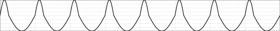
Phase dist offset
Parameter that allows to change the fixed points as well as the one moved in the phase distortion. Below, the same deformation as previously by moving the point located at 3/4 (lower part of the wave):

Sign
Invert the LFO sign. It is used, for example, to transform a rising sawtooth into a descending one:

Polarity
Switching to unipolar. This parameter moves up and compresses the curve so that the bottom is at zero. This mode can simplify the modulation rate settings because the minimum of the LFO corresponds to the basic value of the modulated parameter.

Variation 1, Variation 2
The meaning of these two parameters depends on the selected waveform.
Phase set
Manually sets the phase of the LFO, in degrees. The value 360 does not cause any change. This is useful when you want to apply a preset without changing the current phase.
Graphic editing
You can also adjust the LFO settings with an immediate graphical preview of the waveform.

The parameters can be scrolled as usual, they are displayed one by one at the bottom left. The very first parameter Cycles indicates how many oscillation cycles have to be displayed.
The dots at the bottom right give the precision of the changes obtained with the ← and → keys. This precision can be changed with Select. Esc to go back to the main parameter screen.
V. Troubleshooting
Coming soon… (or not?)
VI. Change log
r52, 2024-02-10
- Added the Bazz Fuzz effect.
r51, 2023-12-12
- Added the Vocoder effect.
r50, 2022-06-07
- Crystalise is now an effect of its own.
r49, 2022-06-03
- Added crystalise effect in Spectal Freeze.
r48, 2022-03-04
- Added a keyboard picture on the PEq GUI.
- Added the CPU usage display per single effect.
r47, 2021-12-12
- Added the Lipidipi effect.
r46, 2021-10-31
- Added the Bad Radio effect.
r45, 2021-05-26
- Added Spectral Freeze and Velvet Freeze effects.
r44, 2021-05-24
- Added Send and Return devices to the audio routing to create internal feedback loops.
r43, 2021-05-05
- Added a few parameters on Spectral Crusher.
r42, 2021-05-02
- Added the Spectral Crusher effect.
r41, 2021-04-27
- Added LShift and RShift modifier keys.
r40, 2020-12-12
- Added several utility effects : Channel merge, Channel split, Convert to mono, Mid-side coder and Stereo panning.
r39, 2020-12-05
- Added the Volume Clone effect.
r38, 2020-12-04
- Added the Platitude reverberation effect.
r37, 2020-11-18
- Added the Big Muff Pi emulation.
r36, 2020-11-13
- Added graphical editing for the CompEx.
r35, 2020-11-02
- Added an amplitude parameter to the ADSR envelope generator.
r34, 2020-04-03
- Added Skool-Mood, an emulation of the Uni-Vibe phaser.
r33, 2020-03-08
- Added the « Toggle FX » pedal action.
r32, 2020-03-26
- Added the Diode clipper effect.
r31, 2020-03-24
- Added Moog filter simulation.
r30, 2020-03-09
- Added the possibility to insert an effect after another and not only before.
r29, 2020-02-04
- Added waveshaper figures.
r28, 2020-02-02
- Added the Distortion 3 effect.
r27, 2020-01-21
- Added the Automatic param assign option in the Other settings menu.
r26, 2020-01-18
- Added Frequency splitter effect.
r25, 2020-01-17
- Added routing functionalities, program settings.
- Updated the screenshots.
r24, 2019-11-09
- Added the audio recording page.
r23, 2019-11-02
- Adapted the manual for Pédale Vite version 2.
r22, 2019-07-24
- Updated the bank organisation and the other settings screens.
r21, 2019-07-18
- Added graphical editing for the LFO.
- Fixed broken hypertext links.
r20, 2019-07-17
- Added the ADSR effect.
r19, 2019-07-16
- The LFO now comes in two flavours, the normal one and the slow one.
r18, 2019-07-02
- Added the All-Pass Distortion effect.
r17, 2019-06-02
- Added the Pulse Width Modulation Distortion 2 effect.
r16, 2018-10-29
- Added the Test Generator.
r15, 2018-09-27
- Added the Hypercomb effect.
r14, 2018-08-26
- Updated the documentation to reflect the recent changes (Ramp, LFO, modulation editing).
r13, 2018-05-28
- Added the bank organizing screens.
r12, 2018-04-03
- Added the Onset Detector effect.
- Updated available modulation curves.
- Updated user interface screens.
r11, 2018-03-22
- Added the Pitch Detector effect.
r10, 2017-08-01
- Added the Phaser AP effect.
r9, 2017-07-17
- Added the Color Me effect.
- Updated several user interface screens.
r8, 2017-06-14
- Added the SiemensGirlz effect.
r7, 2017-04-24
- Added the Ramp effect.
r6, 2017-04-22
- Added new parameters to the envelope detector.
- Added a second wah effect.
r5, 2017-02-11
- Moved the notch part of Noise Bleach into a second effect named Noise Chlorine.
r4, 2017-02-11
- Added continuous band filtering to Noise Bleach.
r3, 2017-02-07
- Added fiver parameters to the phase.
r2, 2017-02-05
- Added the Noise bleach effect.
r1, 2017-01-28
- Added the Harmonic tremolo effect.
r0, 2016-11-29
- First document release.